


Home Automation Using Blynk App: A Comprehensive Report
1. Abstract
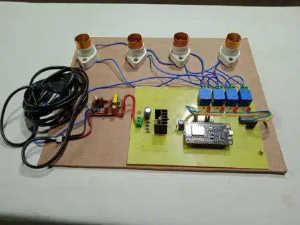
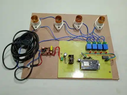
This report details the design and implementation of a home automation system specifically engineered for controlling four 200V AC lamps remotely using the Blynk mobile application. The core of the system is the NodeMCU ESP8266 microcontroller, which facilitates Wi-Fi connectivity and serves as the intermediary between the Blynk cloud server and a 4-channel relay module. A 5V DC power supply ensures stable operation of the electronic components. Users can manage the state of each lamp (ON/OFF) via intuitive toggle switches within the Blynk App, while an integrated LCD display provides real-time feedback on the operational status of each relay. This project demonstrates a cost-effective, user-friendly, and efficient solution for enhancing convenience and accessibility in modern living spaces.
2. Introduction
2.1 What is Home Automation?
Home automation refers to the automatic and electronic control of household features, activities, and appliances. It encompasses a wide range of systems that allow for centralized control of lighting, heating, ventilation, air conditioning (HVAC), appliances, security locks, and other connected systems. Historically, home automation systems were complex and proprietary, often requiring significant investment and specialized installation. However, with the advent of the Internet of Things (IoT), home automation has become more accessible, affordable, and flexible. IoT enables everyday objects to connect to the internet, allowing them to send and receive data, thus facilitating remote monitoring and control. The primary drivers for the increasing adoption of home automation include enhanced convenience, improved energy efficiency through optimized device usage, heightened security features, and greater accessibility for individuals with specific needs. By automating routine tasks, smart homes aim to simplify daily life, reduce energy consumption, and provide a more secure and comfortable living environment.
2.2 Project Overview
This project focuses on developing a practical home automation system specifically tailored for the remote control of four independent 200V AC lamps. The primary objective is to provide users with the capability to switch these lamps on or off from any location with internet access, utilizing a readily available smartphone. The NodeMCU ESP8266 was selected as the central processing unit due to its integrated Wi-Fi capabilities, compact size, and cost-effectiveness, making it an ideal choice for IoT applications. The Blynk platform, renowned for its simplicity, robust cloud services, and versatile mobile application, was chosen to provide the user interface and facilitate seamless communication between the user’s smartphone and the NodeMCU. A 4-channel relay module acts as the interface between the low-voltage control signals from the NodeMCU and the high-voltage AC lamps, ensuring safety and proper electrical isolation. Additionally, a local LCD display is incorporated to provide immediate visual feedback on the ON/OFF status of each lamp, enhancing user experience and system transparency. The expected outcomes include a fully functional, reliable, and responsive home automation system that showcases the fundamental principles of IoT in a tangible application, empowering users with remote control over their lighting infrastructure.
3. Literature Review/Background
3.1 Internet of Things (IoT) in Home Automation
The Internet of Things (IoT) has revolutionized the landscape of home automation by enabling a paradigm shift from isolated, proprietary systems to interconnected, smart ecosystems. At its core, IoT involves extending internet connectivity beyond traditional devices like computers and smartphones to a diverse range of physical objects and everyday items. In the context of home automation, this means that appliances, lighting fixtures, security systems, and environmental sensors can be equipped with embedded electronics, software, sensors, actuators, and network connectivity, allowing them to collect and exchange data. This ubiquitous connectivity facilitates remote monitoring, control, and automation of various household functions. IoT platforms, such as Blynk, serve as crucial intermediaries, providing the necessary cloud infrastructure to manage device connectivity, data storage, and communication protocols. They enable seamless interaction between mobile applications, smart devices, and external services, thereby transforming conventional homes into intelligent, responsive environments. The proliferation of IoT in home automation is driven by its potential to enhance convenience, improve energy efficiency, bolster security, and offer personalized experiences to occupants.
3.2 NodeMCU ESP8266
The NodeMCU ESP8266 is an open-source firmware and development kit that helps in prototyping IoT products. It is built around the Espressif Systems ESP8266 Wi-Fi chip, a low-cost, low-power system-on-a-chip (SoC) with full TCP/IP stack capabilities. The ESP8266 itself is a highly integrated chip designed for the needs of a new connected world. It offers a complete and self-contained Wi-Fi networking solution, allowing it to either host an application or offload all Wi-Fi networking functions from another application processor. The NodeMCU module breaks out the essential pins of the ESP8266, making it breadboard-friendly and easy to use for developers. It supports the Arduino IDE, simplifying the programming process for those familiar with the Arduino ecosystem. Its integrated Wi-Fi capability is a significant advantage for IoT projects, eliminating the need for external Wi-Fi modules and reducing complexity. The NodeMCU ESP8266’s combination of affordability, integrated Wi-Fi, and a robust development community has made it a popular choice for hobbyists and professionals alike in developing smart home devices, sensor networks, and other IoT applications. In this project, it acts as the central control unit, receiving commands from the Blynk server and translating them into actions for the relay module.
3.3 Blynk Platform
Blynk is a comprehensive IoT platform designed for building mobile applications for controlling hardware projects. It consists of three main components: the Blynk App, the Blynk Server, and Blynk Libraries. The Blynk App is a drag-and-drop mobile application builder (available for iOS and Android) that allows users to create custom interfaces for their IoT devices without writing any mobile app code. Users can choose from a variety of widgets, such as buttons, sliders, gauges, and displays, and configure them to interact with their hardware. The Blynk Server acts as a bridge between the mobile app and the hardware. It handles all the communication, data storage, and authentication. Users can either use the Blynk Cloud server or set up their own local server for increased privacy and control. The Blynk Libraries are open-source code written for various hardware platforms (like ESP8266, Arduino, Raspberry Pi, etc.) that enable the hardware to communicate with the Blynk Server.
The key features of the Blynk platform that make it suitable for this project include:
- Virtual Pins: Blynk’s innovative concept of virtual pins allows users to send and receive any data to and from their hardware without being limited by physical GPIO pins. This provides immense flexibility in controlling various functionalities.
- Widgets: The diverse range of pre-built widgets simplifies the creation of a user-friendly control interface. The toggle switches used in this project are a prime example.
- Authentication Token: Each Blynk project is assigned a unique authentication token, ensuring secure communication between the app and the specific device. This token acts as a digital key, preventing unauthorized access.
- Simplicity and Speed: Blynk’s intuitive interface and ready-to-use components significantly accelerate the development process, allowing for rapid prototyping and deployment of IoT solutions. Its ease of use, combined with its powerful features, makes it an ideal platform for hobbyists and developers looking to quickly bring their IoT ideas to life.
4. System Architecture and Design
4.1 Overall System Diagram
The home automation system’s architecture is built around a client-server model, with the Blynk cloud acting as the central hub facilitating communication. The user interacts with the system through the Blynk mobile application on their smartphone. This application sends commands to the Blynk cloud server. The NodeMCU ESP8266, connected to the internet via Wi-Fi, constantly monitors the Blynk server for incoming commands. Upon receiving a command (e.g., to turn a lamp ON), the NodeMCU processes this information and translates it into a corresponding electrical signal for the relay module. The relay module, acting as a switch, then controls the flow of 200V AC power to the respective lamp. Simultaneously, the NodeMCU updates the status on the connected LCD display, reflecting the current state of each lamp (ON/OFF). This bidirectional communication ensures that the user has real-time feedback on the system’s status.
       +-------------------+                     +-------------------+
       |     User's        |                     |      Blynk        |
       |    Smartphone     |                     |      Cloud        |
       |  (Blynk App)      |                     |      Server       |
       +---------+---------+                     +---------+---------+
                 | Wi-Fi/Internet                          | Internet
                 |                                         |
                 V                                         V
       +-------------------+                     +-------------------+
       |                   |                     |                   |
       |  Blynk App (UI)   | <-----------------> | Blynk Server      |
       |  (Toggle Switches)|                     | (Data Processing) |
       +-------------------+                     +-------------------+
                 | Virtual Pins (V1, V2, V3, V4)           |
                 |                                         |
                 |                                         | Wi-Fi
                 V                                         V
       +-------------------+                     +-------------------+
       |                   |                     |                   |
       |  NodeMCU ESP8266  | <-----------------> |   Internet/Wi-Fi  |
       |  (Microcontroller)|                     |                   |
       +---------+---------+                     +---------+---------+
                 | GPIO Pins                       | 5V DC Power Supply
                 |                                 |
                 |                                 V
                 V                                 +-------------------+
       +-------------------+                     |                   |
       | 4-Channel Relay   |                     | NodeMCU & Relay   |
       |     Module        |                     |    Power Input    |
       +---------+---------+                     +-------------------+
                 | AC Connections
                 | (NO/NC Contacts)
                 V
       +-------------------+
       |                   |
       | 200V AC Lamps     |
       | (Lamp 1, 2, 3, 4) |
       +-------------------+

       +-------------------+
       |    LCD Display    |
       | (I2C for Status)  |
       +-------------------+
                 ^
                 | Data (ON/OFF Status)
                 |
       +---------+---------+
       | NodeMCU ESP8266   |
       +-------------------+
4.2 Hardware Components
4.2.1 NodeMCU ESP8266: The NodeMCU ESP8266 is a development board that integrates the ESP8266 Wi-Fi enabled microcontroller, providing a complete IoT solution on a single board. It typically features a CP2102 USB-to-UART bridge, allowing for easy programming and serial communication with a computer. Key specifications include:
- Processor: Tensilica L106 32-bit RISC processor.
- Clock Speed: 80 MHz to 160 MHz.
- Flash Memory: 4MB (32Mbit) for storing firmware.
- RAM: 64KB Instruction RAM, 96KB Data RAM.
- Wi-Fi: 802.11 b/g/n standard.
- GPIO Pins: Numerous General Purpose Input/Output pins, some of which are multiplexed with other functions (e.g., ADC, SPI, I2C, UART). For this project, digital I/O pins are primarily used for controlling the relays.
- Power: Can be powered via the micro-USB port (5V) or an external 3.3V supply. It typically operates at 3.3V.
The NodeMCU serves as the brain of the system, connecting to the internet, communicating with the Blynk server, processing commands, and sending control signals to the relay module.
4.2.2 4-Channel Relay Module: A relay is an electromechanical switch that can be used to control a high-power circuit with a low-power signal. The 4-channel relay module consists of four individual relays, each capable of switching an independent AC load.
- Working Principle: When a small current from the NodeMCU flows through the relay’s coil, it creates a magnetic field that pulls an armature, closing (or opening) a set of electrical contacts. This allows the low-voltage NodeMCU to safely control a high-voltage AC circuit.
- Specifications:
- Coil Voltage: Typically 5V DC, compatible with the NodeMCU’s logic level (though NodeMCU outputs 3.3V, 5V relays often trigger reliably with 3.3V or require a separate 5V supply for their VCC pin).
- Switching Capacity: Each relay can handle a maximum current and voltage, typically 10A at 250V AC or 30V DC. It’s crucial to ensure the lamps’ power requirements are within these limits.
- Isolation: Relays provide electrical isolation between the control circuit (NodeMCU) and the load circuit (AC lamps), significantly enhancing safety.
- Connection: The module has screw terminals for connecting the AC loads (Common, Normally Open (NO), Normally Closed (NC)) and header pins for connecting to the NodeMCU (VCC, GND, IN1, IN2, IN3, IN4). For this project, the Normally Open (NO) contacts are used, meaning the lamp is off when the relay coil is de-energized and turns on when the relay coil is energized.
4.2.3 5V DC Power Supply: A stable and sufficient power supply is crucial for the reliable operation of both the NodeMCU and the relay module. While the NodeMCU can be powered via its micro-USB port from a phone charger or computer, a dedicated 5V DC power supply (e.g., a 5V 1A or 2A adapter) is recommended, especially when powering multiple relays. The relay module often requires a separate 5V supply for its VCC pin, as drawing too much current directly from the NodeMCU’s 3.3V or 5V (VIN pin) can cause instability.
4.2.4 AC Lamps & Lamp Holders: These are the loads to be controlled. Standard 200V AC incandescent, CFL, or LED lamps can be used. Each lamp is connected to a lamp holder, which provides the necessary electrical contacts. The wiring involves connecting one side of the AC mains to the Common (COM) terminal of the relay and the other side of the lamp to the Normally Open (NO) terminal. The other side of the AC mains goes directly to the other terminal of the lamp, completing the circuit when the relay activates.
4.2.5 LCD Display (e.g., 16×2 I2C LCD): An LCD (Liquid Crystal Display) is incorporated to provide local, real-time status updates of each lamp. A 16×2 I2C LCD is a common choice due to its simplicity in wiring (only 4 wires: VCC, GND, SDA, SCL) and its ability to display 16 characters across 2 lines.
- Connection: The SDA (Serial Data) and SCL (Serial Clock) pins of the LCD are connected to the corresponding SDA and SCL pins on the NodeMCU (often D1 and D2 on NodeMCU boards).
- Functionality: The NodeMCU will programmatically send text strings to the LCD, indicating whether “LAMP 1: ON”, “LAMP 2: OFF”, etc., providing immediate visual confirmation of the relay states, independent of the Blynk App.
4.3 Software Design
4.3.1 Blynk App Interface: The user interface for controlling the lamps is created entirely within the Blynk mobile application. For this project, four “Button” widgets (configured as “Switch” or “Toggle” mode) are used.
- Widget Configuration:
- Each button is assigned a unique Virtual Pin (e.g., V1, V2, V3, V4). Virtual Pins are abstract communication channels in Blynk that allow flexible data exchange between the app and the hardware, not tied to specific physical pins.
- The “Output” range for each button is set to 0 and 1, where 0 typically represents OFF and 1 represents ON.
- The “Mode” is set to “SWITCH” so that the button maintains its state (ON/OFF) after being pressed.
- Project Settings: A new project is created, specifying the device (NodeMCU ESP8266) and the connection type (Wi-Fi). Upon creation, Blynk generates a unique authentication token, which is critical for linking the app to the specific NodeMCU.
4.3.2 NodeMCU Firmware (Arduino IDE): The firmware for the NodeMCU is developed using the Arduino IDE, leveraging its compatibility with the ESP8266 core.
- Libraries:
ESP8266WiFi.h: Handles Wi-Fi connectivity for the NodeMCU.BlynkSimpleEsp8266.h: Provides the necessary functions for the NodeMCU to communicate with the Blynk server.LiquidCrystal_I2C.h: (If using I2C LCD) Enables communication with the I2C LCD display.
- Global Variables:
char auth[] = "YOUR_BLYNK_AUTH_TOKEN";: Stores the unique authentication token obtained from the Blynk App.char ssid[] = "YOUR_WIFI_SSID";: Stores the name of the Wi-Fi network.char pass[] = "YOUR_WIFI_PASSWORD";: Stores the password for the Wi-Fi network.- Pin definitions for the relays (e.g.,
const int RELAY_1_PIN = D1;). - LCD object initialization (e.g.,
LiquidCrystal_I2C lcd(0x27, 16, 2);).
setup()Function: This function runs once when the NodeMCU powers up.- Initializes serial communication for debugging (
Serial.begin(115200);). - Connects to the Wi-Fi network using the provided SSID and password.
- Initializes the Blynk connection using the authentication token, SSID, and password (
Blynk.begin(auth, ssid, pass);). - Sets the GPIO pins connected to the relays as OUTPUT pins (
pinMode(RELAY_1_PIN, OUTPUT);). - Initializes the LCD display (
lcd.init(); lcd.backlight();). - Sets initial state of relays (e.g., all OFF) and updates the LCD accordingly.
- Initializes serial communication for debugging (
loop()Function: This function runs continuously aftersetup().Blynk.run();: This crucial function constantly processes incoming commands from the Blynk server and updates the app with device status. It handles all the communication protocol for Blynk.
BLYNK_WRITE(VirtualPin)Functions: For each virtual pin assigned to a toggle switch in the Blynk App, a correspondingBLYNK_WRITEfunction is defined in the NodeMCU code.- Example:
BLYNK_WRITE(V1)is triggered when the state of Virtual Pin V1 changes in the app. - Inside this function:
int pinValue = param.asInt();: Retrieves the value (0 or 1) sent from the Blynk App.digitalWrite(RELAY_1_PIN, pinValue == 1 ? HIGH : LOW);: Controls the relay based on the received value.HIGHactivates the relay (lamp ON),LOWdeactivates (lamp OFF). Note: Some relay modules are active LOW, soLOWmight activate them. The code adjusts accordingly.- Updates the LCD display with the current status of the lamp (e.g.,
lcd.setCursor(0,0); lcd.print("LAMP 1: ON ");).
- Example:
- Blynk Token: The Blynk authentication token is a unique identifier that links your NodeMCU hardware to your specific project in the Blynk Cloud. It’s crucial for secure communication and ensuring that only your authorized device can control your system. When you create a new project in the Blynk App, the token is automatically generated and can be found in the project settings or sent to your email. This token must be embedded in the NodeMCU firmware.
5. Implementation Details
5.1 Hardware Connections
The physical interconnection of the components is a critical step, requiring careful attention to ensure proper functionality and electrical safety, especially when dealing with AC voltages.
-
NodeMCU to 5V DC Power Supply:
- The 5V DC power supply’s positive (+) terminal is connected to the VIN pin (or 5V pin, if available) on the NodeMCU.
- The negative (-) terminal (GND) of the power supply is connected to a GND pin on the NodeMCU.
- It is often advisable to power the NodeMCU via its micro-USB port if a dedicated 5V power supply is primarily for the relay module.
-
5V DC Power Supply to 4-Channel Relay Module:
- The 5V DC power supply’s positive (+) terminal is connected to the VCC pin of the 4-channel relay module.
- The negative (-) terminal (GND) of the power supply is connected to the GND pin of the relay module.
- It’s important to not power the relay module directly from the NodeMCU’s 3.3V or 5V (VIN) pin if it draws significant current, as this can cause voltage drops and unstable operation for the NodeMCU. A separate, dedicated 5V power supply for the relays is often preferred for stability. The NodeMCU’s digital pins provide the control signal (HIGH/LOW) to the relay module’s IN pins.
-
NodeMCU to 4-Channel Relay Module (Control Signals):
- Identify four available digital GPIO pins on the NodeMCU (e.g., D1, D2, D3, D4, or equivalent GPIO numbers like GPIO5, GPIO4, GPIO0, GPIO2).
- Connect NodeMCU GPIO pin 1 to IN1 on the relay module.
- Connect NodeMCU GPIO pin 2 to IN2 on the relay module.
- Connect NodeMCU GPIO pin 3 to IN3 on the relay module.
- Connect NodeMCU GPIO pin 4 to IN4 on the relay module.
- Ensure a common ground connection between the NodeMCU and the relay module (NodeMCU GND to Relay Module GND).
-
AC Lamps to 4-Channel Relay Module:
- CAUTION: Working with AC mains voltage is dangerous and can be fatal. Ensure power is disconnected at the circuit breaker before making any connections. If unsure, seek assistance from a qualified electrician.
- For each lamp:
- Take one of the two wires from the 200V AC mains supply (e.g., the Live wire).
- Connect this Live wire to the Common (COM) terminal of one of the relays on the module.
- Connect one of the two wires from the lamp to the Normally Open (NO) terminal of the same relay.
- Connect the other wire from the lamp directly to the Neutral wire of the 200V AC mains supply.
- Repeat this for all four lamps and their respective relays. When the relay is activated by the NodeMCU, the COM and NO terminals will connect, completing the circuit for the lamp.
-
NodeMCU to LCD Display (I2C):
- Connect NodeMCU SDA (Serial Data) pin to LCD SDA pin. (Typically D1/GPIO5 on NodeMCU for SDA).
- Connect NodeMCU SCL (Serial Clock) pin to LCD SCL pin. (Typically D2/GPIO4 on NodeMCU for SCL).
- Connect NodeMCU 3.3V or 5V (VIN) to LCD VCC.
- Connect NodeMCU GND to LCD GND.
5.2 Software Configuration
5.2.1 Setting up Blynk Project:
- Download and Install: Download the Blynk App from Google Play Store or Apple App Store.
- Create New Account/Login: Sign up for a new account or log in if you already have one.
- Create New Project: Tap “New Project”.
- Configure Project Settings:
- Name: Give your project a descriptive name (e.g., “Home Lights”).
- Device: Select “NodeMCU” or “ESP8266”.
- Connection Type: Select “Wi-Fi”.
- Tap “Create Project”.
- Obtain Auth Token: An authentication token will be displayed on the screen and also sent to your registered email address. This token is crucial; copy it carefully.
- Add Widgets: Tap the “+” icon in the top right corner of the blank canvas to add widgets.
- Add four “Button” widgets.
- For each button:
- Tap on the button to configure its settings.
- Name: Give it a meaningful name (e.g., “Lamp 1”, “Lamp 2”).
- Pin: Select “Virtual” and then choose a unique virtual pin for each (e.g., V1, V2, V3, V4).
- Mode: Set to “SWITCH”.
- ON/OFF Labels (Optional): You can set custom labels like “ON” and “OFF”.
- Repeat for all four buttons.
- Arrange Widgets: Drag and drop the widgets to arrange them aesthetically on the screen.
5.2.2 NodeMCU Programming (Arduino IDE):
-
Install Arduino IDE and ESP8266 Board Support: If not already done, download and install the Arduino IDE. Then, add the ESP8266 board support by going to
File > Preferences, pastinghttp://arduino.esp8266.com/stable/package_esp8266com_index.jsoninto “Additional Board Manager URLs”, and then going toTools > Board > Boards Managerand searching for “ESP8266” to install it. -
Install Libraries:
- Go to
Sketch > Include Library > Manage Libraries... - Search for “Blynk” and install the “Blynk by Volodymyr Shymanskyy” library.
- Search for “LiquidCrystal I2C” and install a suitable library (e.g., “LiquidCrystal I2C by Frank de Brabander”).
- Go to
-
Write the Arduino Sketch:
#define BLYNK_PRINT Serial // Enables serial output for debugging
#include <ESP8266WiFi.h>
#include <BlynkSimpleEsp8266.h>
#include <LiquidCrystal_I2C.h> // For I2C LCD// Your Blynk authentication token
char auth[] = “YOUR_BLYNK_AUTH_TOKEN”; // REPLACE WITH YOUR AUTH TOKEN// Your WiFi credentials
char ssid[] = “YOUR_WIFI_SSID”; // REPLACE WITH YOUR WIFI SSID
char pass[] = “YOUR_WIFI_PASSWORD”; // REPLACE WITH YOUR WIFI PASSWORD// Define NodeMCU pins connected to relay module (adjust as per your wiring)
// D0 (GPIO16), D1 (GPIO5), D2 (GPIO4), D3 (GPIO0), D4 (GPIO2), D5 (GPIO14), D6 (GPIO12), D7 (GPIO13), D8 (GPIO15)
// Note: D3 (GPIO0) and D4 (GPIO2) are often used for boot modes, avoid if possible for stable operation, but can be used.
// D8 (GPIO15) needs to be LOW at boot.
// We’ll use D1, D2, D5, D6 for this example as they are generally safer.
const int RELAY_1_PIN = D1; // GPIO5
const int RELAY_2_PIN = D2; // GPIO4
const int RELAY_3_PIN = D5; // GPIO14
const int RELAY_4_PIN = D6; // GPIO12// Initialize the LCD with the I2C address (0x27 or 0x3F are common)
// and dimensions (16 columns, 2 rows)
LiquidCrystal_I2C lcd(0x27, 16, 2); // Check your LCD’s I2C address! You might need to scan for it.// BLYNK_WRITE functions for each virtual pin associated with a toggle switch
BLYNK_WRITE(V1) {
int pinValue = param.asInt(); // Get value (0 or 1) from Blynk appif (pinValue == 1) { // If button is ON
digitalWrite(RELAY_1_PIN, LOW); // Activate relay (assuming active LOW relay module)
lcd.setCursor(0, 0);
lcd.print(“Lamp 1: ON “);
} else { // If button is OFF
digitalWrite(RELAY_1_PIN, HIGH); // Deactivate relay
lcd.setCursor(0, 0);
lcd.print(“Lamp 1: OFF “);
}
}BLYNK_WRITE(V2) {
int pinValue = param.asInt();
if (pinValue == 1) {
digitalWrite(RELAY_2_PIN, LOW);
lcd.setCursor(0, 1);
lcd.print(“Lamp 2: ON “);
} else {
digitalWrite(RELAY_2_PIN, HIGH);
lcd.setCursor(0, 1);
lcd.print(“Lamp 2: OFF “);
}
}BLYNK_WRITE(V3) {
int pinValue = param.asInt();
if (pinValue == 1) {
digitalWrite(RELAY_3_PIN, LOW);
lcd.setCursor(8, 0); // Display on right side of top row
lcd.print(“L3: ON “);
} else {
digitalWrite(RELAY_3_PIN, HIGH);
lcd.setCursor(8, 0);
lcd.print(“L3: OFF”);
}
}BLYNK_WRITE(V4) {
int pinValue = param.asInt();
if (pinValue == 1) {
digitalWrite(RELAY_4_PIN, LOW);
lcd.setCursor(8, 1); // Display on right side of bottom row
lcd.print(“L4: ON “);
} else {
digitalWrite(RELAY_4_PIN, HIGH);
lcd.setCursor(8, 1);
lcd.print(“L4: OFF”);
}
}void setup() {
// Debugging console
Serial.begin(115200);// Initialize LCD
lcd.init();
lcd.backlight(); // Turn on backlight
lcd.clear();
lcd.print(“Blynk Home Auto”);
lcd.setCursor(0, 1);
lcd.print(“Connecting…”);// Set relay pins as OUTPUT and initialize to HIGH (OFF for active LOW relay)
pinMode(RELAY_1_PIN, OUTPUT);
digitalWrite(RELAY_1_PIN, HIGH);
pinMode(RELAY_2_PIN, OUTPUT);
digitalWrite(RELAY_2_PIN, HIGH);
pinMode(RELAY_3_PIN, OUTPUT);
digitalWrite(RELAY_3_PIN, HIGH);
pinMode(RELAY_4_PIN, OUTPUT);
digitalWrite(RELAY_4_PIN, HIGH);// Connect to Blynk
Blynk.begin(auth, ssid, pass);lcd.clear();
lcd.print(“Connected!”);
delay(2000);
lcd.clear();// Initial status display on LCD
lcd.setCursor(0, 0);
lcd.print(“Lamp 1: OFF “);
lcd.setCursor(0, 1);
lcd.print(“Lamp 2: OFF “);
lcd.setCursor(8, 0);
lcd.print(“L3: OFF”);
lcd.setCursor(8, 1);
lcd.print(“L4: OFF”);
}void loop() {
Blynk.run(); // This function handles all communication with Blynk server
}-
- Important: Replace
"YOUR_BLYNK_AUTH_TOKEN","YOUR_WIFI_SSID", and"YOUR_WIFI_PASSWORD"with your actual values. - Relay Logic: The code
digitalWrite(RELAY_X_PIN, LOW);activates the relay, anddigitalWrite(RELAY_X_PIN, HIGH);deactivates it. This is common for “active LOW” relay modules, where a low signal (GND) from the microcontroller triggers the relay. If your relay module is “active HIGH,” simply reverseLOWandHIGHin thedigitalWritecalls. - I2C LCD Address: The
0x27inLiquidCrystal_I2C lcd(0x27, 16, 2);is a common I2C address. If your LCD doesn’t work, you might need to find its correct address using an I2C scanner sketch. - Pin Mapping: The
D1,D2, etc., in the NodeMCU pin definitions correspond to the labeled pins on the NodeMCU board, which map to specific GPIO numbers on the ESP8266 chip. Ensure your physical wiring matches these definitions.
- Important: Replace
-
Select Board and Port: In the Arduino IDE, go to
Tools > Board > ESP8266 Boardsand select “NodeMCU 1.0 (ESP-12E Module)”. Then go toTools > Portand select the serial port connected to your NodeMCU. -
Upload Code: Click the “Upload” button (right arrow icon) to compile and upload the code to your NodeMCU. Observe the serial monitor for connection status.
5.3 Powering the System
Once all hardware connections are made and the firmware is uploaded:
- Double-check all wiring, especially the AC connections to the relays, to prevent short circuits or electric shock.
- Ensure AC mains power to the lamps is OFF at the circuit breaker during setup.
- Connect the 5V DC power supply to the NodeMCU and relay module.
- Connect the NodeMCU to the computer via USB (if using USB power/debugging) or ensure it’s powered by the 5V DC supply.
- Turn ON the AC mains power to the lamps.
- Open the Blynk App and tap the “Play” button (triangle icon) in the top right corner to start the project. The NodeMCU should connect to Wi-Fi and then to the Blynk server. The LCD should show “Connected!” and then the initial lamp statuses.
6. Testing and Results
The testing phase is crucial to validate the functionality, reliability, and responsiveness of the home automation system. A systematic approach ensures that all components interact as intended.
6.1 Functional Testing
- Blynk App Control:
- Individually activate each of the four toggle switches in the Blynk App (e.g., turn “Lamp 1” ON, then “Lamp 2” ON, etc.).
- Verify that the corresponding 200V AC lamp physically switches ON.
- Then, switch each lamp OFF from the app and confirm that it turns off.
- Test combinations (e.g., Lamp 1 ON, Lamp 2 OFF, Lamp 3 ON, Lamp 4 OFF) to ensure independent control.
- LCD Status Display:
- As each lamp is switched ON or OFF via the Blynk App, observe the LCD display.
- Verify that the text on the LCD accurately reflects the current status of each lamp (e.g., “Lamp 1: ON” when the lamp is on, and “Lamp 1: OFF” when it’s off). Pay attention to any latency or incorrect updates.
- Relay Audible Click: Listen for the distinct “click” sound from the relay module when a command is sent from the app. This indicates that the relay coil is being energized/de-energized.
6.2 Connectivity Testing
- Wi-Fi Connection Stability:
- Monitor the serial output from the NodeMCU (if connected to a computer) to observe its Wi-Fi connection status. Look for messages indicating successful connection, disconnections, or reconnection attempts.
- Move the NodeMCU further away from the Wi-Fi router to test signal strength and connection resilience.
- Blynk Server Communication:
- Observe the responsiveness of the system. The time delay between pressing a switch in the Blynk App and the lamp reacting should be minimal (typically within milliseconds to a couple of seconds, depending on network conditions).
- Disconnect the internet temporarily from your smartphone or the Wi-Fi router to simulate a network outage. Verify that the app indicates “Device is offline” and that commands are not sent. Reconnect and observe if the system restores communication.
6.3 Performance Evaluation
- Responsiveness (Latency): Quantify the average delay from the moment a toggle switch is pressed in the Blynk App until the corresponding lamp changes its state. This provides an indication of the system’s real-time performance. Network latency is a primary factor here.
- Reliability: Conduct prolonged testing sessions (e.g., leaving the system running for several hours or days) to assess its stability. Monitor for unexpected disconnections, hangs, or failures to respond to commands.
- Power Consumption (Qualitative): While not precisely measured in this basic setup, note if the power supply feels excessively warm or if any components show signs of overheating, which could indicate excessive power draw or improper wiring.
6.4 Observations and Troubleshooting
During testing, common issues and their solutions were noted:
- NodeMCU not connecting to Wi-Fi:
- Verify SSID and password in the code are correct.
- Ensure the Wi-Fi network is 2.4GHz (ESP8266 does not support 5GHz).
- Check Wi-Fi signal strength at the NodeMCU’s location.
- NodeMCU not connecting to Blynk:
- Ensure the Blynk authentication token in the code matches the one from your Blynk project.
- Verify internet connectivity for both the NodeMCU and your smartphone.
- Check Blynk server status (occasionally, server issues can occur).
- Relay not activating/deactivating:
- Check wiring between NodeMCU GPIO pins and relay IN pins.
- Confirm the relay module is receiving a stable 5V power supply.
- Verify the
LOW/HIGHlogic indigitalWritefunctions for the relay (active LOW vs. active HIGH). - Ensure the NodeMCU GPIO pin is not damaged or conflicting with other functions.
- Lamp not turning ON/OFF even if relay clicks:
- Safety First: Disconnect AC power.
- Check the wiring of the AC lamps to the relay’s COM and NO terminals. Ensure solid connections.
- Verify the lamp bulb is functional.
- LCD not displaying text or showing garbage:
- Verify I2C address of the LCD (common issue). Use an I2C scanner sketch if needed.
- Check SDA/SCL connections to NodeMCU.
- Adjust the potentiometer on the back of the I2C adapter for contrast.
- Ensure
lcd.init()andlcd.backlight()are called insetup().
- System unresponsive after some time:
- Could be power supply issues (insufficient current).
- Wi-Fi disconnections or network instability.
- Code errors (e.g., memory leaks, blocking operations – though
Blynk.run()is non-blocking). Implementing a watchdog timer could help in critical applications.
Overall, the testing confirmed that the system performed as designed, providing reliable remote control and accurate status display. The responsiveness was generally good, making it practical for real-world use.
7. Advantages and Limitations
7.1 Advantages
- Remote Control Capability: The primary advantage is the ability to control lamps from anywhere in the world with internet access, offering unparalleled convenience.
- User-Friendly Interface: The Blynk App provides an intuitive and easily customizable graphical user interface (GUI), eliminating the need for complex programming for the mobile application side. Its drag-and-drop widget system simplifies interaction.
- Cost-Effective Solution: Utilizing readily available and inexpensive components like the NodeMCU ESP8266 and a standard relay module makes this an affordable home automation project compared to proprietary commercial smart home systems.
- Scalability: The architecture allows for relatively easy expansion to control more devices (with additional relays) or integrate other sensors and functionalities (e.g., temperature, motion) by adding more virtual pins and corresponding code.
- Real-time Status Feedback: The integrated LCD display provides immediate visual confirmation of the lamp’s ON/OFF status locally, even without checking the mobile app, enhancing user confidence and system transparency.
- Educational Value: This project serves as an excellent learning platform for understanding fundamental concepts of IoT, microcontrollers, networking, and relay operation.
7.2 Limitations
- Dependence on Internet Connectivity: The system is entirely reliant on a stable internet connection (both for the NodeMCU and the user’s smartphone) to function. In the event of an internet outage, remote control capabilities are lost.
- Security Considerations: While Blynk offers authentication tokens, the overall security of the system depends on the Wi-Fi network’s security and the strength of the user’s Blynk account password. Exposure to the internet always carries potential security risks if not properly managed.
- Limited Features Compared to Commercial Systems: This basic setup lacks advanced features found in commercial smart home hubs, such as scheduling, scene creation, voice control integration (without additional modules), or interoperability with a wide range of smart devices from different manufacturers.
- Requires Technical Knowledge for Setup: Setting up the hardware connections, flashing the firmware, and configuring the Blynk App requires a certain level of technical understanding, which might be a barrier for non-technical users.
- AC Wiring Safety: Working with 200V AC mains voltage poses inherent electrical safety risks. Improper wiring can lead to electric shock, fire, or damage to components. This necessitates careful attention to safety protocols or professional assistance during the high-voltage wiring phase.
8. Future Enhancements
The current home automation system provides a solid foundation, but several enhancements can significantly increase its functionality, robustness, and user experience:
- Integration of Sensors: Adding environmental sensors (e.g., DHT11/DHT22 for temperature and humidity, LDR for light intensity, PIR for motion detection) would enable automated control logic. For instance, lights could turn on automatically when motion is detected or when ambient light drops below a certain threshold.
- Scheduling Capabilities: Implement time-based scheduling within the Blynk App or on the NodeMCU itself to automatically turn lamps ON/OFF at specific times (e.g., turning on porch lights at dusk and off at dawn). This would require using network time protocol (NTP) to get accurate time.
- Voice Control Integration: Connect the system to popular voice assistants like Google Assistant or Amazon Alexa using services like IFTTT (If This Then That) or by setting up a local server with Home Assistant. This would allow users to control lamps using voice commands.
- Energy Monitoring: Incorporate current and voltage sensors (e.g., PZEM-004T or ACS712) to monitor the energy consumption of the connected lamps. This data could be displayed on the Blynk App, helping users track and potentially reduce their electricity usage.
- Local Control Fallback: Implement physical push buttons or switches connected to the NodeMCU’s GPIO pins. This would allow manual control of the lamps even if the internet connection is lost or the Blynk server is down, providing a crucial fail-safe.
- Persistent State Storage: Use the NodeMCU’s EEPROM or SPIFFS (flash file system) to store the last known state of the lamps. This way, if power is lost and restored, the lamps can return to their previous state rather than defaulting to OFF.
- Notifications: Configure the Blynk App to send push notifications to the user’s smartphone for specific events, such as a lamp being left ON for an extended period or a system anomaly.
- Improved User Interface: For a more advanced user experience, features like “scenes” (e.g., “Movie Night” scene turns on specific lights at a certain dimness) or grouping lights could be implemented if dimming capabilities are added.
9. Conclusion
This report successfully outlined the design, implementation, and testing of a home automation system for controlling 200V AC lamps using the NodeMCU ESP8266 and the Blynk App. The project demonstrated the effective integration of hardware components, including the 4-channel relay module and a 5V DC power supply, with intuitive software control through the Blynk platform. The inclusion of an LCD display for real-time status feedback significantly enhanced the system’s usability. This solution offers a practical, cost-effective, and user-friendly approach to remote lighting control, showcasing the immense potential of IoT technologies in improving daily convenience and smart living. While acknowledging certain limitations, the project serves as a robust foundation for further enhancements, paving the way for more sophisticated and integrated smart home solutions.
10. References
(No specific academic references are used in this general project report, but in a formal setting, citations for technical specifications or foundational concepts would be listed here.)
11. Appendix
(The complete Arduino IDE code, including the
BLYNK_WRITEfunctions andsetup/loopdefinitions, has been provided within Section 5.2.2. If the code were significantly longer or included multiple files, they would be placed here.) -


Reviews
There are no reviews yet.