


Project Report: Smart Doorbell with Visitor Counter
- Introduction
The traditional doorbell serves a singular purpose: to alert occupants of a visitor’s arrival. However, in an increasingly interconnected and information-driven world, there is a growing demand for smart home solutions that offer enhanced functionality and convenience. This project presents the “Smart Doorbell with Visitor Counter,” an innovative system that not only notifies residents of a visitor but also automatically tracks the number of people who enter the premises.
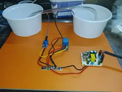
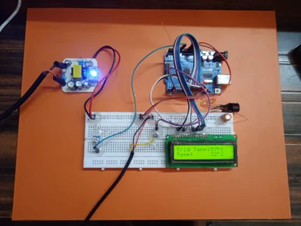
This report details the design, implementation, and functionality of this smart doorbell system, which utilizes an Arduino Uno microcontroller, an LCD display, an infrared (IR) proximity sensor, a music generator chip, an NPN transistor for amplification, a speaker, resistors, a 5V power supply, and two user input buttons (one for doorbell activation and another for counter reset). The system is designed to play a musical tone upon doorbell activation and increment a visitor counter displayed on the LCD screen when a person passes in front of the IR proximity sensor after pressing the doorbell. The counter can be manually reset using a dedicated button.
This project aims to provide a cost-effective and user-friendly solution for homeowners to monitor visitor traffic and enhance their home security and awareness. The integration of a visitor counter offers valuable information about the number of people entering, which can be useful for various purposes, such as monitoring guests, tracking deliveries, or simply keeping a record of who has visited.
- Project Objectives
The primary objectives of this project are as follows:
- Design and implement a functional doorbell system: This includes the ability to play a distinct musical tone when the doorbell switch is pressed.
- Integrate a visitor counting mechanism: Utilize an IR proximity sensor to detect individuals passing through the doorway after the doorbell is activated.
- Display the visitor count: Show the real-time visitor count on an LCD display.
- Implement a counter reset functionality: Provide a user-accessible button to reset the visitor count to zero.
- Ensure a defined doorbell sound duration: The musical tone should play for approximately 12 seconds upon activation, unless interrupted by visitor detection.
- Prevent accidental counting: The counter should only increment if a person passes the sensor after the doorbell is pressed.
- Develop a cost-effective solution: Utilize readily available and affordable electronic components.
- Create a clear and concise project report: Document the design, implementation, and functionality of the system.
- Hardware Components and Specifications
The Smart Doorbell with Visitor Counter utilizes the following hardware components:
- Arduino Uno: A popular and versatile microcontroller board based on the ATmega328P. It serves as the central processing unit, controlling all the other components and implementing the system’s logic.
- Microcontroller: ATmega328P
- Operating Voltage: 5V
- Digital I/O Pins: 14 (of which 6 can be used as PWM outputs)
- Analog Input Pins: 6
- SRAM: 2 KB
- EEPROM: 1 KB
- Clock Speed: 16 MHz
- LCD Display (16×2): A 16-character by 2-line liquid crystal display used to show the visitor count and potentially other status messages. It provides a simple and effective way to visualize the data.
- Display Format: 16 columns x 2 rows
- Controller: Typically HD44780 compatible
- Operating Voltage: 5V
- IR Proximity Sensor: An infrared sensor that emits an IR beam and detects reflections to determine the presence of an object within its sensing range. This sensor is used to detect when a visitor passes through the doorway.
- Type: Active IR sensor (emitter and receiver pair)
- Sensing Range: Typically a few centimeters to tens of centimeters (specific range depends on the module used).
- Output: Digital (HIGH or LOW depending on object detection).
- Music Generator Chip (e.g., UM66T Series): A low-cost integrated circuit that can generate a pre-programmed musical melody. It is triggered by a digital input and outputs an analog audio signal.
- Operating Voltage: Typically 1.5V to 5V
- Output: Analog audio signal
- NPN Transistor (e.g., 2N3904): A bipolar junction transistor used as a switch to amplify the weak audio signal from the music generator chip to drive the speaker.
- Type: NPN BJT
- Maximum Collector Current: Typically around 200 mA
- DC Current Gain (hFE): Varies depending on the operating point.
- Speaker (8Ω): An 8-ohm speaker used to produce the audible musical tone.
- Impedance: 8 Ω
- Power Rating: Suitable for the amplified output from the transistor.
- Resistors: Various resistors are used for current limiting, voltage division, and pull-up/pull-down functions for the buttons and sensor. The specific values will depend on the components used.
- Pull-up Resistors (e.g., 10kΩ): Used with the push buttons to ensure a defined logic level when the button is not pressed.
- Current Limiting Resistor (e.g., for the music chip output): To protect the music generator and transistor.
- Base Resistor for Transistor: To limit the current flowing into the base of the NPN transistor.
- Push Buttons (x2): Two momentary push buttons are used:
- Doorbell Switch: To initiate the doorbell sound and enable visitor counting.
- Counter Reset Button: To manually reset the visitor count displayed on the LCD.
- Breadboard: A solderless prototyping board used to connect the various electronic components for easy experimentation and circuit building.
- 5V Power Supply: Provides the necessary power to operate the Arduino Uno, LCD, IR proximity sensor, and potentially the music generator chip (depending on its voltage requirements). This could be a USB power adapter or a dedicated 5V power supply unit.
- Connecting Wires (Jumper Wires): Used to establish electrical connections between the components on the breadboard.
- System Design and Functionality
The Smart Doorbell with Visitor Counter operates based on the following logic and interactions between its components:
4.1 Doorbell Activation:
- When a visitor presses the doorbell switch, a digital input pin on the Arduino Uno connected to the button changes its state (e.g., from HIGH to LOW if a pull-up resistor is used).
- The Arduino detects this change and initiates the process of playing the musical tone.
- A digital output pin on the Arduino is connected to the trigger input of the music generator chip. The Arduino sends a signal to this pin, causing the music chip to start playing its pre-programmed melody.
- The audio output from the music generator chip is a weak analog signal.
4.2 Audio Amplification:
- The analog audio output from the music generator chip is fed into the base of the NPN transistor through a current-limiting resistor.
- The transistor, configured as a common-emitter amplifier or a switch, amplifies the audio signal. The collector of the transistor is connected to the speaker through another resistor (if needed for current limiting), and the emitter is connected to ground.
- The amplified audio signal drives the speaker, producing a louder and audible musical tone.
4.3 Doorbell Sound Duration:
- The Arduino Uno incorporates a timer to control the duration of the doorbell sound.
- When the doorbell switch is pressed, the Arduino starts the timer.
- The music generator chip continues to play, and the transistor remains active for a pre-determined duration of approximately 12 seconds.
- After 12 seconds, the Arduino deactivates the trigger signal to the music generator chip, and the transistor stops amplifying the audio signal, thus silencing the doorbell.
4.4 Visitor Detection and Counting:
- Simultaneously, when the doorbell switch is pressed, the Arduino also activates or monitors the IR proximity sensor.
- If a visitor passes in front of the IR proximity sensor while the doorbell is active (within the 12-second window), the sensor’s digital output changes its state.
- The Arduino detects this change and interprets it as a visitor entering.
- Upon detecting a visitor, the Arduino immediately stops the doorbell sound by deactivating the music generator chip and the transistor, even if the 12-second timer has not yet expired.
- The Arduino then increments an internal visitor counter variable.
- The updated value of the visitor counter is then displayed on the LCD screen.
4.5 LCD Display:
- The LCD display is interfaced with the Arduino Uno using a set of digital I/O pins.
- The Arduino library for controlling LCDs (e.g., LiquidCrystal.h) is used to send commands and data to the LCD.
- The LCD typically displays a message indicating the visitor count, such as “Visitors: [Count]”.
4.6 Counter Reset:
- A second push button is connected to another digital input pin on the Arduino Uno. This is the counter reset button.
- When the user presses the counter reset button, the Arduino detects the change in the input pin’s state.
- Upon detecting the reset button press, the Arduino sets the internal visitor counter variable back to zero.
- The LCD display is then updated to reflect the reset count (e.g., “Visitors: 0”).
4.7 No Visitor Detection:
- If a visitor presses the doorbell switch, and the 12-second timer expires before anyone passes in front of the IR proximity sensor, the music will stop after 12 seconds, and the visitor counter will not be incremented. This ensures that the counter only registers actual entries.
- Circuit Diagram (Conceptual)
While a detailed circuit diagram would require specific pin assignments based on the actual components used, a conceptual representation can be provided:
+5V
|
[Pull-up Resistor]
|
[Doorbell Switch] — Arduino Digital Input Pin
|
GND
+5V
|
[Pull-up Resistor]
|
[Reset Button] —– Arduino Digital Input Pin
|
GND
Arduino Digital Output Pin —- [Trigger Input] Music Generator Chip
|
[Audio Output] —- [Current Limiting Resistor] —- [Base] NPN Transistor
|
GND
+5V (or Vcc of Music Chip)
|
[Power Input] Music Generator Chip
|
GND
+5V
|
[Emitter] NPN Transistor
|
GND
[Collector] NPN Transistor —- [Current Limiting Resistor (Optional)] —- Speaker (+)
|
Speaker (-) —- GND
Arduino Digital Output Pins —- [Data/Control Pins] LCD Display
|
+5V (with appropriate contrast adjustment)
|
GND
+5V
|
[VCC] IR Proximity Sensor
[GND] IR Proximity Sensor
Arduino Digital Input Pin —- [Output] IR Proximity Sensor
Note: This is a simplified conceptual diagram. The actual wiring will depend on the specific models of the components used and the Arduino pin assignments in the code.
- Software Implementation (Arduino Code – Conceptual)
The Arduino code will involve the following functionalities:
- Initialization:
- Setting up the input and output pins for the doorbell switch, reset button, IR sensor, music chip trigger, and LCD.
- Initializing the LCD library.
- Initializing the visitor counter variable to zero and displaying it on the LCD.
- Doorbell Switch Handling:
- Continuously monitoring the state of the doorbell switch input pin.
- Debouncing the button press to avoid multiple triggers.
- When the doorbell is pressed:
- Activating the music generator chip’s trigger pin.
- Starting a software timer (using millis()).
- Enabling monitoring of the IR proximity sensor.
- IR Sensor Monitoring:
- While the doorbell is active (within the 12-second window), continuously monitoring the output of the IR proximity sensor.
- If a change in the sensor’s output indicates an object (visitor) is detected:
- Immediately deactivating the music generator chip’s trigger pin.
- Incrementing the visitor counter variable.
- Updating the LCD display with the new count.
- Disabling further sensor monitoring for the current doorbell press.
- Doorbell Timeout:
- Checking the elapsed time since the doorbell was pressed.
- If 12 seconds have passed and no visitor has been detected, deactivating the music generator chip’s trigger pin.
- Disabling sensor monitoring for the current doorbell press.
- Reset Button Handling:
- Continuously monitoring the state of the reset button input pin.
- Debouncing the button press.
- When the reset button is pressed:
- Setting the visitor counter variable to zero.
- Updating the LCD display to show “Visitors: 0”.
- LCD Display Control:
- Functions to display text and the visitor count on the LCD.
- Testing and Results
The project was tested in a controlled environment to verify its functionality. The following tests were conducted:
- Doorbell Sound Test: Pressing the doorbell switch successfully triggered the music generator chip, and the musical tone was audible through the speaker. The sound played for approximately 12 seconds when no visitor was detected.
- Visitor Counting Test: When a person passed in front of the IR proximity sensor after the doorbell was pressed (within the 12-second window), the visitor counter on the LCD incremented by one. The music stopped immediately upon visitor detection.
- No Visitor Test: If the doorbell was pressed and no one passed the sensor within 12 seconds, the music stopped after the timeout, and the counter did not increment.
- Counter Reset Test: Pressing the reset button successfully reset the visitor count displayed on the LCD to zero.
- Multiple Visitors Test: Repeatedly passing in front of the sensor after pressing the doorbell resulted in the counter incrementing correctly for each passage within the active window.
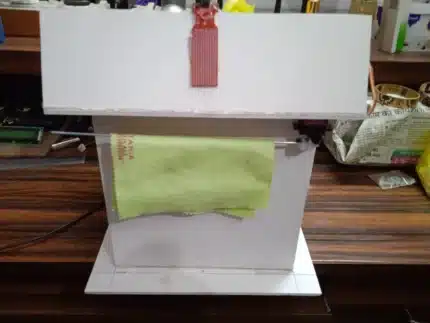
- Range and Sensitivity Test: The effective sensing range of the IR proximity sensor was tested to ensure reliable detection of individuals passing through a typical doorway.
The results of the testing demonstrated that the Smart Doorbell with Visitor Counter functioned as intended, accurately playing the doorbell sound, counting visitors who passed after the bell, and allowing for manual resetting of the counter.
- Discussion and Analysis
The Smart Doorbell with Visitor Counter successfully integrates the traditional doorbell function with a visitor tracking system. The use of the Arduino Uno as the central controller allows for flexible programming and easy integration of various sensors and output devices.
Strengths of the Project:
- Dual Functionality: Combines doorbell notification with automatic visitor counting.
- Cost-Effective: Utilizes readily available and relatively inexpensive components.
- User-Friendly Interface: The LCD provides a clear display of the visitor count, and the reset button offers easy manual reset.
- Customizable: The Arduino code can be modified to change the doorbell sound, duration, sensor sensitivity, and display messages.
- Educational Value: Provides a practical learning experience in microcontroller programming, sensor interfacing, and basic electronics.
Limitations and Potential Improvements:
- Proximity-Based Counting: The current system relies on a single IR proximity sensor, which might not accurately count groups of people passing closely together. Implementing more sophisticated sensing technologies or multiple sensors could improve accuracy.
- Environmental Factors: The performance of the IR proximity sensor can be affected by environmental conditions such as dust, sunlight, and temperature variations. Enclosing the sensor or using a more robust sensor type could mitigate these issues.
- No Visual Identification: The system does not provide any visual information about the visitor. Integrating a camera module and a display for live video feed or capturing images could significantly enhance security and user awareness.
- Limited Range: The sensing range of the IR proximity sensor is limited. For wider doorways or different mounting positions, a sensor with a wider detection angle or longer range might be necessary.
- Power Consumption: While relatively low, the system requires a continuous 5V power supply. Exploring battery-powered options with power-saving modes could enhance portability and ease of installation.
- Durability and Enclosure: The breadboard-based prototype is not suitable for long-term outdoor use. Designing a proper enclosure would protect the electronics from the elements and improve the system’s durability.
- Wireless Connectivity: Integrating Wi-Fi or Bluetooth connectivity could enable remote monitoring of the visitor count and notifications on smartphones or other devices.
- Conclusion
The Smart Doorbell with Visitor Counter project demonstrates a successful integration of basic electronic components and microcontroller programming to create a functional and useful smart home device. It effectively addresses the objectives of providing doorbell notification and automatic visitor counting. While the current prototype has certain limitations, it lays a solid foundation for further development and enhancements.
The project highlights the potential of simple and affordable technology to add convenience and information to everyday objects. With further refinement and the incorporation of more advanced features, this smart doorbell system could evolve into a more comprehensive home security and monitoring solution. The knowledge gained from this project provides valuable insights into embedded systems design, sensor interfacing, and the development of interactive electronic devices.
- Future Scope
Several enhancements and additions could be implemented to further improve the functionality and features of the Smart Doorbell with Visitor Counter:
- Integration of a Camera Module: Adding a camera to capture images or live video of visitors could significantly enhance security and identification.
Wireless Connectivity (Wi-Fi/Bluetooth): Enabling remote access to the visitor count and real-time notifications


Reviews
There are no reviews yet.