

3-Phase Transmission Line Fault Detector
- Introduction
The transmission of electrical power over long distances is essential for ensuring that electricity is delivered to consumers. However, faults such as short circuits, ground faults, and phase-to-phase faults can occur in transmission lines, leading to power outages and potential hazards. Detecting and isolating these faults quickly is critical for maintaining the reliability of the electrical grid. This project focuses on designing a 3-phase transmission line fault detector using an Arduino Uno, relays, sensors, and display modules.
The system is designed to detect and identify faults in a 3-phase transmission system, including both phase-to-ground faults and phase-to-phase faults. The fault detection system is designed to trip the transmission lines when a fault is detected and restore normal operation when the fault is cleared.
- Objective
The objective of this project is to design and implement a fault detection system for a 3-phase transmission line. The system will:
- Monitor the status of the three phases.
- Detect faults such as phase-to-ground and phase-to-phase faults.
- Automatically isolate faulty phases by triggering relay modules to trip the lines.
- Use a flame sensor to detect abnormal conditions and trip the system in case of dangerous conditions.
- Display the status of the system on an I2C LCD screen.
- Simulate faults at different distances using a resistance network.
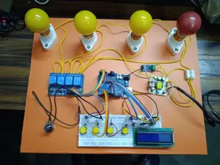
- System Components
The system uses the following components:
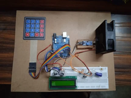
- Arduino Uno: The main microcontroller for processing inputs and controlling outputs.
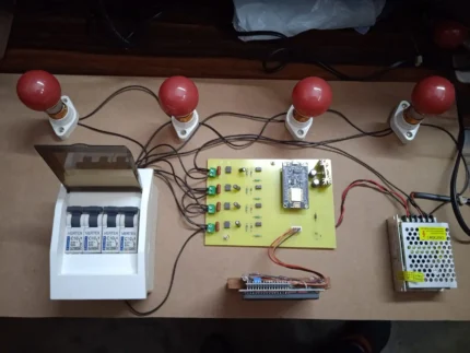
- 4-Channel Relay Module: Three relay modules control the three phases of the transmission line.
- 5V Power Supply: Powers the Arduino and other components.
- Breadboard: Used to set up and interconnect the components.
- Flame Sensor: Detects the presence of a flame and triggers the fault detection system.
- I2C LCD Module: Displays the status of the system, including fault types and phase status.
- Lamps and Lamp Holders: Represent the three phases in the system, showing the status of each phase (on/off).
- Push Buttons (12 total): Used to simulate faults in the transmission line, including phase-to-ground and phase-to-phase faults.
- Resistor Network: Simulates different fault distances by creating variable resistance between phases, simulating faults at various locations on the transmission line.
- Working Principle
The system operates by continuously monitoring the state of the three phases. Here’s how each part works:
- Flame Detection: The flame sensor is continuously monitored by the Arduino. If a flame is detected, the system automatically trips all three phases, disconnecting the transmission line to prevent further damage or risk.
- Fault Simulation: The push buttons simulate faults. Twelve buttons are used to simulate phase-to-ground faults (one for each phase), while another set of twelve buttons simulate phase-to-phase faults. By pressing the appropriate button, the corresponding fault is created in the system, and the Arduino detects it using the input pins.
- Relay Activation: When a fault is detected, the corresponding phase is disconnected by the relay. The relay is controlled by the Arduino using a digital output signal.
- Phase Indication: The three lamps represent the three phases of the transmission line. When the corresponding relay is closed, the lamp is turned on, indicating normal operation. When the relay is opened (in case of a fault), the lamp is turned off, indicating the faulted phase.
- Resistance Network: The resistor network simulates fault conditions at different locations on the transmission line by varying the resistance between phases. Higher resistance corresponds to faults occurring further away from the source, while lower resistance corresponds to faults occurring closer to the source.
- Fault Detection Mechanism
- Phase-to-Ground Fault: A phase-to-ground fault occurs when one of the phases comes into contact with the ground. This type of fault is detected when the corresponding push button for that phase is pressed, and the Arduino identifies the fault condition.
- Phase-to-Phase Fault: A phase-to-phase fault occurs when two phases come into contact with each other. This is detected when the appropriate push button is pressed to simulate the fault, and the Arduino isolates the faulty phases.
- Flame Detection: The flame sensor continuously monitors for the presence of a flame. If a flame is detected, all three phases are automatically tripped by the relay system to avoid potential damage due to fire or overheating.
- System Block Diagram
The system consists of the following main blocks:
- Arduino Uno: Main controller, processes inputs and controls relays.
- Relays: Control the phases of the transmission line, disconnecting the faulty phases.
- Flame Sensor: Monitors for fire and triggers the system to trip all phases.
- Push Buttons: Simulate faults in the system.
- Lamps: Indicate the status of the three phases.
- LCD Module: Displays the fault type, phase status, and any other relevant information.
(This is a placeholder for the block diagram image)
- Flowchart
The flowchart outlines the system’s operation:
- Start
- Check for Flame Detection: If flame detected, trip all phases.
- Monitor Push Buttons for Faults:
- If a phase-to-ground fault button is pressed, disconnect the corresponding phase.
- If a phase-to-phase fault button is pressed, disconnect the two corresponding phases.
- Display Fault Information on LCD
- Control Relays to Trip Faulty Phases
- Wait for Normal Operation: Once the fault is cleared, restore the system to normal operation.
- Repeat.
- System Operations
- Normal Condition: All phases are operational. The relays are closed, the lamps are on, and the LCD displays that the system is functioning normally.
- Flame Detection: The flame sensor detects a fire. The system trips all three phases, the lamps turn off, and the LCD displays “Flame Detected – System Tripped”.
- Fault Simulation:
- Pressing a push button for a phase-to-ground fault disconnects the corresponding phase. The lamp for the affected phase turns off, and the LCD shows “Phase-to-Ground Fault Detected”.
- Pressing a push button for a phase-to-phase fault disconnects the affected phases. The corresponding lamps turn off, and the LCD shows “Phase-to-Phase Fault Detected”.
- Circuit Diagram
A detailed circuit diagram is shown above, illustrating how the components are connected:
- Conclusion
The 3-phase transmission line fault detection system provides an efficient method for monitoring and isolating faults in a transmission system. By using an Arduino Uno, relay modules, a flame sensor, and an LCD display, the system is able to detect and isolate faults in real-time, ensuring the protection of electrical infrastructure and improving the reliability of power transmission. The addition of a resistance network allows for the simulation of faults at different distances, making this system a valuable tool for testing and educational purposes.
- Future Enhancements
Future improvements to this project could include:
- Integration with real-time data monitoring systems for remote fault detection.
- Use of more advanced sensors (such as temperature sensors) to detect other fault conditions.
- Implementing automatic restoration of the system after a fault is cleared.
- Adding wireless communication (e.g., Wi-Fi or GSM) for remote notifications and control.
This system can be further expanded and fine-tuned to be used in more complex and large-scale electrical systems.


Reviews
There are no reviews yet.