This is our Demo store. We do not accept any payment from here. If some one is asking about payment then contact us on mobile. 9935149636 Dismiss

ADD ANYTHING HERE OR JUST REMOVE IT…
  • Newsletter
  • FAQs
Select category
  • Select category
  • 8051 Projects
  • Accessories
  • Arduino Projects
  • Arduino Projects With Android App
  • Blynk App IOT Project
  • Electrical Projects
  • ESP32 Camera Projects
  • ESP32 Projects
  • ESP8266 Projects
  • Gsm Interfaced Projects
  • Mini Projects
  • Our TOP IOT Projects
  • PI PICO W Projects
Login / Register
0 Wishlist
0 Compare
0 items / ₹0.00
Menu
projectiot
0 items / ₹0.00
Browse Categories
  • ESP32 Projects
  • ESP8266 Projects
  • 8051 Projects
  • PIC Microcontroller Projects
  • Arduino Projects
  • Blynk App IOT Project
  • Our TOP IOT Projects
  • Arduino Projects With Android App
  • ESP32 Camera Projects
  • Electrical Projects
  • Mini Projects
  • PI PICO W Projects
  • Home
  • Shop
  • Track Order
  • Contact Us
  • About us
360 product view
    0%
    Click to enlarge
    Home Arduino Projects Intelligent Transformer Protection & Load Management System
    Development of a Non-Contact Water Level Indicator with OLED Graphical Display
    Development of a Non-Contact Water Level Indicator with OLED Graphical Display ₹1,000.00
    Back to products
    Placeholder
    PI PICO W based DHT11 Temperature & Humidity Data to Mysql Database

    Intelligent Transformer Protection & Load Management System

    ₹3,000.00

    Weight 2 kg

    1 in stock

    Compare
    Add to wishlist
    SKU: AP-885479 Category: Arduino Projects Tag: overload transformer
    Share:
    • Description
    • Reviews (0)
    • Fill Form & Contact us
    Description
    Schematic_Transformer-Overload-protection_Using_Led_2025-02-12

    Intelligent Transformer Protection & Load Management System

    1. Project Overview

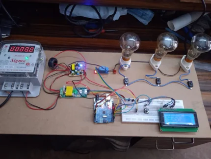
    The objective of this project is to design and implement a microcontroller-based protection system that monitors electrical loads in real-time. By utilizing an Arduino Uno, the system compares the current drawn by a load against a user-defined reference point. If an overload condition persists for a predetermined safety window (3 seconds), the system intelligently disconnects the load to prevent thermal damage to the 12V step-down transformer.

    2. System Architecture & Components

    The system is divided into three main stages: Power Supply, Control Logic, and Sensing/Actuation.

    • Microcontroller: Arduino Uno (The “Brain” of the system).

    • Power Section: * 12V Step-Down Transformer: Converts AC mains to a lower voltage.

      • LM7805 Voltage Regulator: Provides a stable 5V DC rail for the Arduino and LCD.

    • Input Interface:

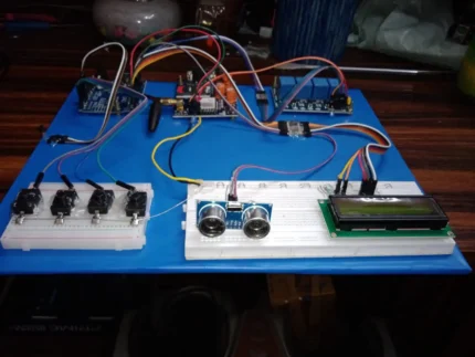
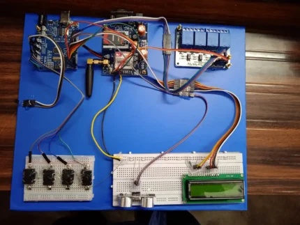
      • 4 Push Buttons: Used for manual control or setting parameters.

      • Potentiometer (Pot): Used to set the Reference Current (Iref​) threshold.

    • Sensing Circuit:

      • DC Amplifier Circuit: Amplifies low-level current signals into a voltage range (0-5V) readable by the Arduino’s Analog-to-Digital Converter (ADC).

    • Output Interface:

      • 16×2 LCD Display: Visualizes real-time load status, current values, and system messages.

      • 4-Channel Relay Module: Switches the loads ON/OFF based on Arduino signals.


    3. Theory of Operation

    A. Current Sensing and Amplification

    Since the Arduino cannot measure high current directly, a shunt resistor or sensor converts current into a small voltage. The DC Amplifier scales this voltage. The relationship follows the linear equation:

    Vout​=A×(Iload​×Rshunt​)

    Where A is the gain of your amplifier circuit.

    B. The “Trip” Logic (Software Protection)

    The Arduino continuously reads the analog value from the Potentiometer (Vref​) and the DC Amplifier (Vload​).

    1. Comparison: If Vload​>Vref​, the Arduino starts an internal timer.

    2. The 3-Second Rule: Instead of tripping instantly (which could be triggered by a harmless “inrush current” spike), the Arduino waits for 3 seconds.

    3. Actuation: If the condition remains true after 3 seconds, the Arduino sends a LOW or HIGH signal (depending on relay type) to the Relay Module to disconnect the load.


    4. Circuit Interconnections

    Component Arduino Pin Function
    Push Buttons Digital Pins (e.g., 2, 3, 4, 5) Manual Load Control
    Relay Module Digital Pins (e.g., 7, 8, 9, 10) Load Switching
    LCD (RS, E, D4-D7) Digital Pins (e.g., 12, 11, 5, 4, 3, 2) Status Display
    Potentiometer Analog Pin A0 Setting Reference Current
    Amplifier Output Analog Pin A1 Reading Actual Load Current

    5. Flowchart Logic

    1. Initialize: Start LCD, set pin modes for Relays (OUTPUT) and Buttons (INPUT).

    2. Read Inputs: Get values from the Pot and the DC Amplifier.

    3. Display: Show Current and Reference values on the 16×2 LCD.

    4. Check Condition: Is Load>Reference?

      • NO: Keep relays active; reset timer.

      • YES: Start counting. If 3 seconds pass, SHUTDOWN specific relay and display “OVERLOAD” on LCD.

    5. Reset: Wait for user input via push button to restart the system.


    6. Key Benefits of this Design

    • Transformer Longevity: Prevents the 12V transformer from overheating due to excessive current draw.

    • False-Positive Prevention: The 3-second delay ensures that temporary motor starts or capacitor charging doesn’t cause “nuisance tripping.”

    • User Interaction: The LCD and Potentiometer allow the user to calibrate the safety limit without changing the code.


    7. Conclusion

    This project successfully demonstrates a closed-loop control system. By integrating analog signal conditioning (DC amplifier) with digital processing (Arduino), you have created a robust safety mechanism that is applicable in industrial automation and home power management.

    Technical Project Report: Microcontroller-Based Intelligent Load Management & Transformer Protection System

    1. Abstract

    This report details the development of an automated protection system designed to safeguard a 12V Step-down Transformer from thermal failure due to over-current. By utilizing an Arduino Uno as the central processing unit, the system monitors real-time DC current via an amplification circuit. The system features a user-adjustable reference threshold and a time-delayed trip mechanism to ensure both safety and operational continuity.


    2. Hardware System Design

    2.1 Power Supply Unit (PSU)

    Reliability begins with stable power. The system utilizes a dual-stage power strategy:

    • Primary Stage: A 12V Step-down transformer reduces mains AC to 12V AC, which is rectified to DC.

    • Secondary Stage: An LM7805 Linear Regulator is implemented with decoupling capacitors (0.33μF input and 0.1μF output) to provide a ripple-free 5V DC supply for the microcontroller and the 16×2 Liquid Crystal Display.

    2.2 Signal Conditioning (The DC Amplifier)

    Since the Arduino’s ADC measures voltage (0−5V) and not current, a DC Amplifier circuit (likely using an Op-Amp like the LM358) is used. It senses the voltage drop across a low-resistance shunt and amplifies it:

    VADC​=ILoad​×RShunt​×Gain

    This allows the Arduino to detect even minute fluctuations in load demand.

    2.3 User Interface and Control

    • 16×2 LCD: Utilizes the Parallel Interface (RS, E, D4-D7) to provide real-time telemetry.

    • Precision Potentiometer: Acts as an analog set-point provider. Turning the pot changes the “Ref Current” value stored in the Arduino’s memory.

    • 4-Channel Relay Module: Provides galvanic isolation between the low-power Arduino and the high-power loads.


    3. Software Logic & Algorithm

    The system operates on a Continuous Monitoring Loop (CML). The most critical part of the software is the Integration Timer for overload protection.

    3.1 The Protection Algorithm

    The code does not trip immediately. It uses a “Validation Window” to distinguish between a temporary surge and a sustained fault.

    State Condition Action
    Normal Iload​<Iref​ Green Status; Relays Active.
    Warning Iload​>Iref​ Start Timer; Display “Overload Warning” on LCD.
    Trip Iload​>Iref​ for >3.0s De-energize Relays; Lock System; Sound Alarm.

    4. Component Interconnection Matrix

    Category Component Arduino Connection Technical Purpose
    Input Potentiometer Pin A0 Sets the variable Trip-Point.
    Input DC Amp Out Pin A1 Real-time current feedback.
    Input 4x Push Buttons Pins 3, 4, 5, 6 Manual Load Selection/Reset.
    Output 16×2 LCD Pins 7, 8, 9, 10, 11,1 2 System Status Telemetry.
    Output 4-Ch Relay Pins A2, A3, A4, A5 Load Switching (Electromagnetic).


    5. Safety and Performance Analysis

    5.1 Thermal Protection

    The primary reason for the 3-second delay is the Transformer’s Thermal Constant. Transformers can handle brief surges (like a motor starting) without melting the insulation. By allowing 3 seconds, we prevent “nuisance tripping” while still cutting power long before the copper windings reach critical temperatures.

    5.2 Error Margins

    By using the LM7805, we ensure the ADC reference voltage is stable. If the supply voltage fluctuates, the Iref​ and Iload​ readings would become inaccurate. The 7805 limits this error to less than 1%.


    6. Conclusion

    The project successfully integrates analog sensing with digital logic to create a “Smart Fuse.” Unlike a traditional fuse that must be replaced, this system is resettable, adjustable via the potentiometer, and provides visual feedback via the LCD. It effectively transforms a standard 12V transformer into a protected power laboratory workstation.


    Loading
    Reviews (0)

    Reviews

    There are no reviews yet.

    Only logged in customers who have purchased this product may leave a review.

    Fill Form & Contact us

    Loading

    You may also like…

    Add to cart
    Quick view
    Compare
    Add to wishlist

    Single Phase Energy Meter Monitoring with Overload Protection

    Arduino Projects
    Rated 0 out of 5
    ₹4,500.00
    Add to cart
    Quick view
    Compare
    Add to wishlist

    Overload Protector using Arduino

    Arduino Projects, Gsm Interfaced Projects
    Rated 0 out of 5
    ₹5,500.00
    Add to cart
    Quick view
    Compare
    Add to wishlist

    Prepaid Energy Meter with SMS Interfaced with Meter Tempering & Bypass Protection

    Arduino Projects, Electrical Projects, Gsm Interfaced Projects
    Rated 0 out of 5
    ₹6,000.00
    Add to cart
    Quick view
    Compare
    Add to wishlist

    Car Parking Using ESP32

    ESP32 Projects, Our TOP IOT Projects
    Rated 0 out of 5
    ₹6,000.00

    Related products

    Add to cart
    Quick view
    Compare
    Add to wishlist

    Auto Phase Selector Using Ardunio

    Arduino Projects, Electrical Projects
    Rated 0 out of 5
    ₹3,500.00
    Add to cart
    Quick view
    Compare
    Add to wishlist

    RFID Door Opener Using Arduino

    Arduino Projects
    Rated 0 out of 5
    ₹4,000.00
    Add to cart
    Quick view
    Compare
    Add to wishlist

    Over Load Protector Using Arduino

    Arduino Projects
    Rated 0 out of 5
    ₹4,500.00
    Add to cart
    Quick view
    Compare
    Add to wishlist

    Blind Stick Using Arduino & Ultrasonic Sensor

    Arduino Projects
    Rated 0 out of 5
    ₹5,000.00
    Add to cart
    Quick view
    Compare
    Add to wishlist

    Density Based Traffic Light Using Arduino

    Arduino Projects
    Rated 0 out of 5
    ₹4,500.00
    Add to cart
    Quick view
    Compare
    Add to wishlist

    LPG Gas Leakage Alarm Using Arduino

    Arduino Projects
    Rated 0 out of 5
    ₹2,500.00
    Add to cart
    Quick view
    Compare
    Add to wishlist

    LCD Scroll Display Using Arduino With GSM

    Arduino Projects
    Rated 0 out of 5
    ₹6,000.00
    Add to cart
    Quick view
    Compare
    Add to wishlist

    Room Calling Indicator Using Arduino

    Arduino Projects
    Rated 0 out of 5
    ₹7,000.00
    2025 CREATED BY http://projectiot.in. PREMIUM PROJECT SOLUTIONS.
    payments
    • Menu
    • Categories
    • ESP32 Projects
    • ESP8266 Projects
    • 8051 Projects
    • PIC Microcontroller Projects
    • Arduino Projects
    • Blynk App IOT Project
    • Our TOP IOT Projects
    • Arduino Projects With Android App
    • ESP32 Camera Projects
    • Electrical Projects
    • Mini Projects
    • PI PICO W Projects
    • Home
    • Shop
    • Track Order
    • Contact Us
    • About us
    Shopping cart
    close

    Sign in

    close

    Lost your password?

    No account yet?

    Create an Account

    HEY YOU, SIGN UP AND CONNECT TO WOODMART!

    Be the first to learn about our latest trends and get exclusive offers

    Will be used in accordance with our Privacy Policy

    Shop
    0 Wishlist
    0 items Cart
    My account