


Arduino-Based Early Earthquake & Seismic Vibration Alert System
1. Executive Summary
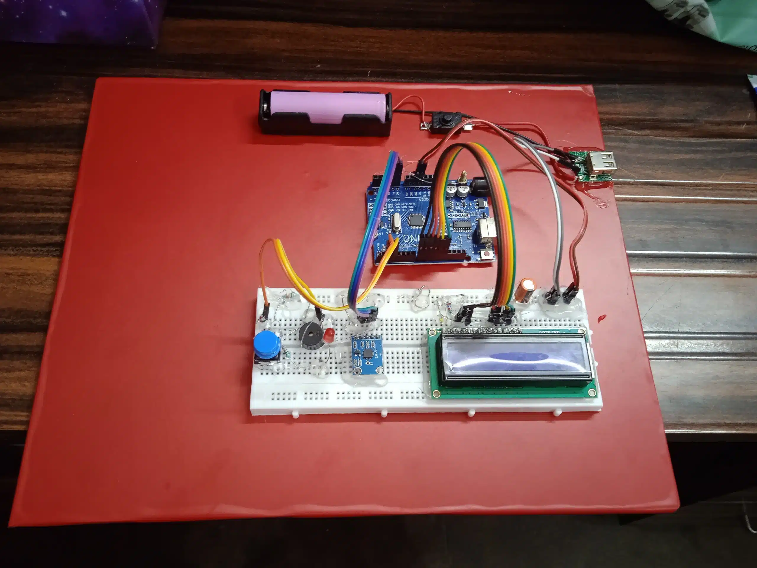
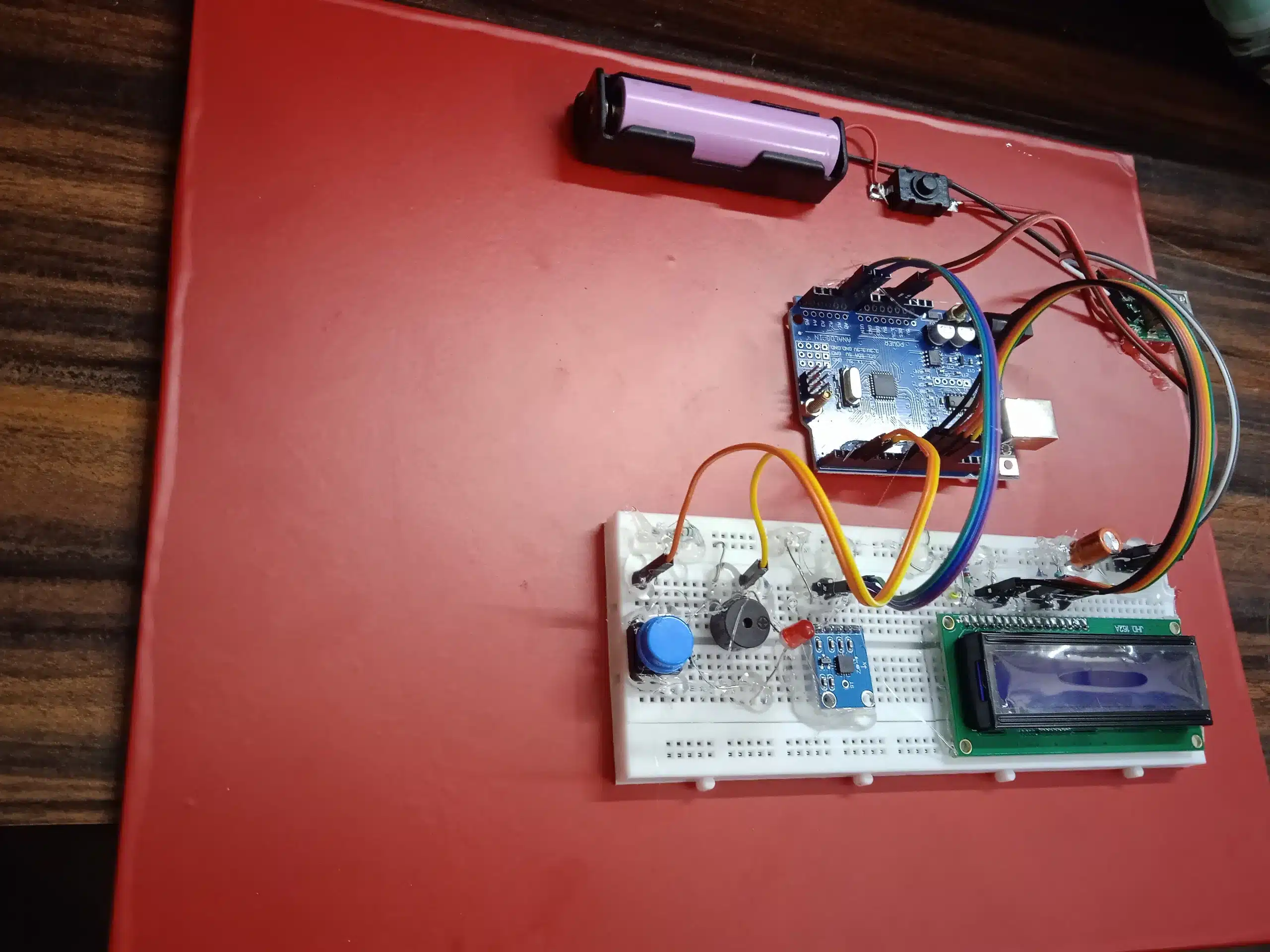
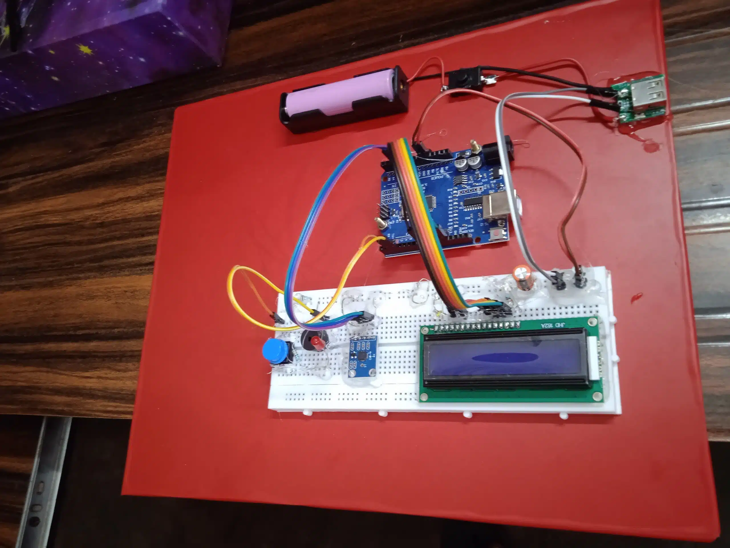
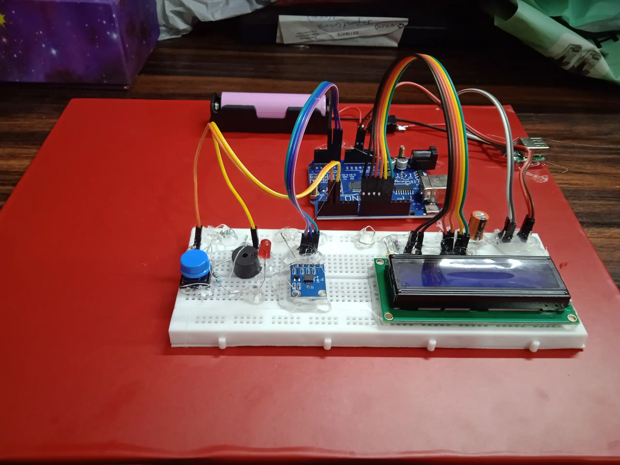
Seismic activity poses significant risks to human life and structural integrity. Immediate localized warning systems provide critical seconds required to initiate automated safety measures or evacuation protocols. This project details the design, hardware integration, algorithm development, and testing of a standalone, battery-operated seismic vibration detector. Powered by an Arduino Uno and utilizing an ADXL335 3-axis MEMS accelerometer, the system captures real-time dynamic motion, compares live signals against a user-calibrated baseline, and activates an instantaneous audiovisual alarm when threshold levels are breached.
2. Project Objectives & Features
- Real-time Seismic Sensing: Detect abrupt spatial displacements and low-to-high frequency tilt/vibrations across 3 axes (X,Y,Z).
- User-Initiated Calibration: Include a dedicated physical switch to capture ambient resting offset values, eliminating false triggers caused by structural mounting angles or surface tilt.
- Dual-Alert Mechanism: Trigger a high-decibel piezo buzzer and high-luminance LED during detection events.
- Visual Status Interface: Display operational state (“Initializing”, “Calibrating”, “Ready”, “EARTHQUAKE DETECTED”) on a Liquid Crystal Display (LCD).
- Uninterrupted Power System (UPS): Integrate an onboard 18650 Li-ion cell paired with a 5V boost converter module, ensuring system operation during primary power grid failures.
3. Hardware Architecture & Component Specification
3.1 Component List
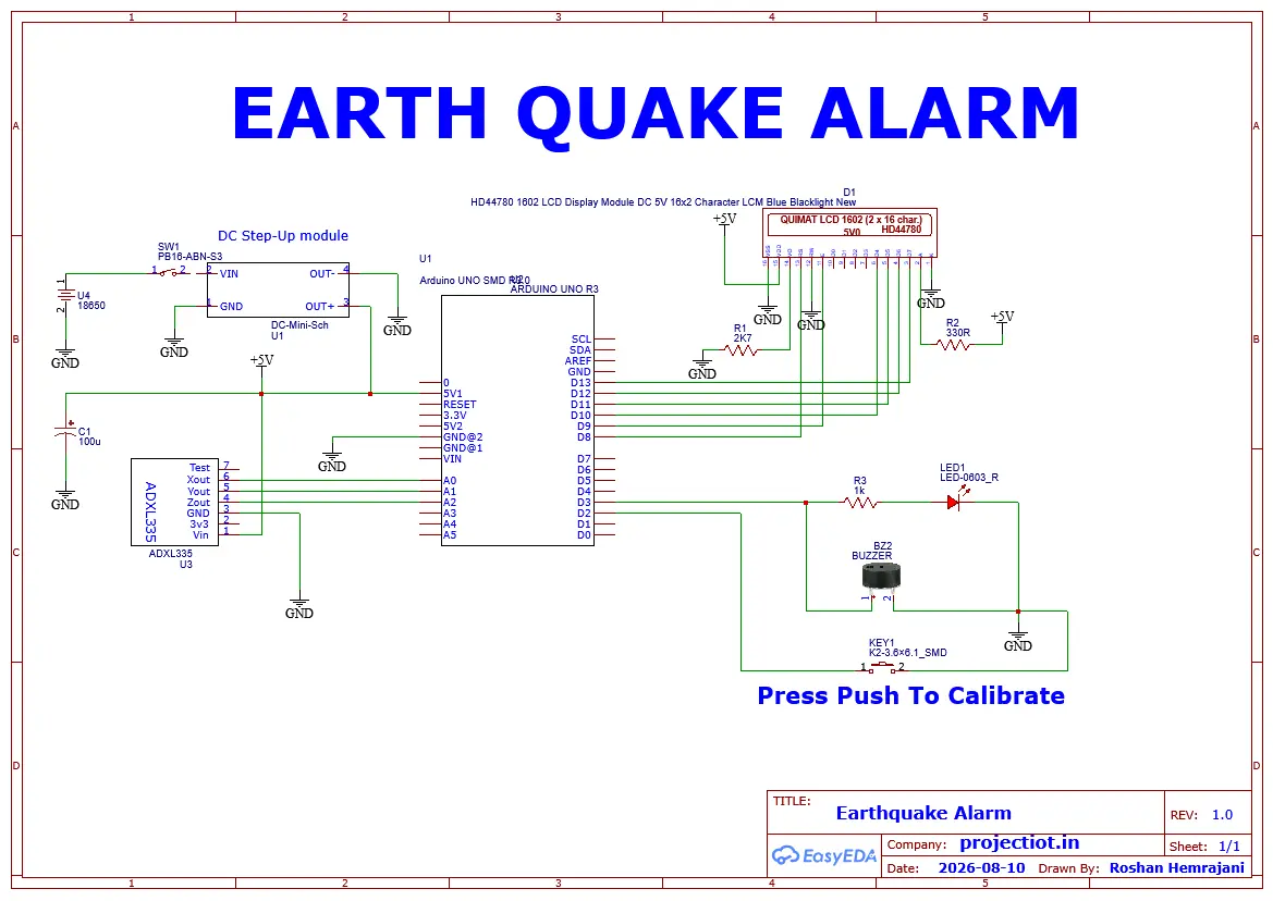
- Arduino Uno (ATmega328P): Central processing unit executing ADC sampling, calibration routines, mathematical comparison, and peripheral triggers.
- ADXL335 Sensor: A 3-axis analog accelerometer with a range of ±3g. It translates dynamic acceleration (motion/vibration) and static acceleration (gravity) into proportional analog voltages.
- LCD Display (16×2): Visual user interface providing operational status, calibration updates, and trigger warnings.
- Piezoelectric Buzzer (5V Active): Audible warning element producing high-pitched acoustic signals.
- Diffused Red LED & 220Ω Resistor: Visual alert component; resistor limits current to protect microcontroller I/O pins.
- 18650 Li-ion Battery & 5V Power Bank Module: Integrated 3.7V to 5V DC-DC step-up converter with charging protection circuit (TP4056-based).
- Control Switches:
- Switch 1 (SPST Rocker/Toggle): Main DC power isolates battery module from the main rail.
- Switch 2 (Momentary Push Button / Toggle): Manual input interrupt for baseline sensor calibration.
- Breadboard & Jumper Wires: Prototyping interconnects.
3.2 Hardware Interconnection & Pinout Mapping
| Component | Component Pin | Arduino Uno Pin | Function / Signal Description |
| ADXL335 | VCC | 3.3V | Power supply (3.3V operational rail) |
| ADXL335 | GND | GND | Common Ground |
| ADXL335 | X-Out | A0 | Analog Signal for X-axis motion |
| ADXL335 | Y-Out | A1 | Analog Signal for Y-axis motion |
| ADXL335 | Z-Out | A2 | Analog Signal for Z-axis motion |
| LCD 16×2 | RS, E, D4, D5, D6, D7 | D12, D11, D5, D4, D3, D2 | Parallel Data & Control Bus |
| LCD 16×2 | VSS, VDD, V0 | GND, 5V, Potentiometer | Power & Contrast control |
| Buzzer | Positive (+) | D8 | Digital Output (High = Alarm ON) |
| Red LED | Anode (+) via 220Ω | D9 | Digital Output (High = Flash LED) |
| Calibration Switch | Terminal 1 | D7 | Digital Input (Internal Pull-Up enabled) |
| Power Module | 5V Out / GND | 5V Pin / GND Pin | System power delivery rail |
4. System Workflow & Control Logic
+——————————————————-+ | Power ON (Switch 1) | +—————————+—————————+ | v +——————————————————-+ | System Initialization & LCD Welcome Screen | +—————————+—————————+ | v +——————————————————-+ | Wait for Calibration (Switch 2) | +—————————+—————————+ | v +——————————————————-+ | Sample Baseline ADC Values (X_base, Y_base, Z_base) | +—————————+—————————+ | v +——————————————————-+ | LCD Displays: “System Ready” | +—————————+—————————+ | v +——————————————————-+ | Continuous Sensor Polling Loop (ADC) | +—————————+—————————+ | v +——————————————————-+ | Calculated Absolute Deviation: | | Delta = |X – X_base| + |Y – Y_base| + |Z – Z_base| | +—————————+—————————+ | +————+————+ | | Delta > Threshold Delta <= Threshold | | v v +—————————-+ +———————–+ | – Trigger LED & Buzzer | | – Mute Buzzer & LED | | – LCD: “EARTHQUAKE ALERT!” | | – LCD: “Status: Normal| +—————————-+ +———————–+
5. Software & Mathematical Model
5.1 Baseline Offset Calibration Algorithm
When mounted on a structure, the sensor rests at a non-zero tilt due to mounting variance and constant Earth gravity (1g acting along the Z-axis or a combination of axes).
When Switch 2 is pressed, the system executes an averaging filter over N=50 consecutive samples to capture stable baseline resting coordinates (Xbase,Ybase,Zbase):
Xbase=N1i=1∑NXraw[i]
Ybase=N1i=1∑NYraw[i]
Zbase=N1i=1∑NZraw[i]
5.2 Seismic Vector Deviation Thresholding
During continuous operation, the system calculates the absolute Manhattan magnitude change Δtotal across all three axes to detect dynamic disturbance:
ΔX=∣Xlive−Xbase∣
ΔY=∣Ylive−Ybase∣
ΔZ=∣Zlive−Zbase∣
Δtotal=ΔX+ΔY+ΔZ
If Δtotal≥Threshold, the state shifts to Alarm Active.
6. Power Management & Autonomy Analysis
- Cell Capacity: 18650 Li-ion cell (7V, 2200 mAh).
- Conversion Efficiency: Booster module operating at ∼85% efficiency step-up to 5V.
- Current Consumption Breakdown:
- Arduino Uno + LCD (Backlight ON): ∼60 mA
- ADXL335 Sensor: ∼350 μA
- Alarm Active State (Buzzer + LED): ∼40 mA additional
- Standby Operational Time:
Total System Draw (Normal)≈60.35 mA
Calculated Runtime=5.0V×60.35 mA2200 mAh×3.7V×0.85≈22.9 Hours continuous operation
7. Limitations & Future Scope
Current Limitations
- Analog Noise Sensitivity: ADXL335 relies on analog signal lines; long wire runs are susceptible to electromagnetic interference (EMI).
- Local Alert Range: Audible buzzer covers immediate indoor spaces but lacks long-range telemetry.
Recommended Future Enhancements
- Digital MEMS Upgrade: Replace ADXL335 with an MPU6050 or ADXL345 (I2C interface) for integrated digital filtering and hardware interrupt generation.
- Telemetry & IoT Integration: Connect an ESP8266/ESP32 or GSM SIM800L module to push immediate SMS and cloud alerts to emergency responders.
- Data Logging: Integrate an SD card module to log raw g-force data for post-event seismic wave analysis.
8. Conclusion
The developed Arduino-based earthquake detector successfully demonstrates a dependable prototype for immediate seismic warning. Through manual baseline calibration, the system effectively compensates for initial sensor orientation, avoiding false alarms. Coupled with an onboard battery backup, this system delivers an accessible, efficient localized early warning solution.


Reviews
There are no reviews yet.