


Arduino-Based Mobile Charging Timer
1. Introduction
In an increasingly interconnected world, mobile devices have become indispensable tools for communication, information access, and entertainment. However, the ubiquitous nature of these devices also brings challenges, one of which is efficient and safe charging. Overcharging, while often mitigated by modern smartphone battery management systems, can still contribute to long-term battery degradation and unnecessary energy consumption. Furthermore, the concept of timed control extends far beyond just mobile charging, offering a versatile solution for managing various household or industrial appliances.
This report details the design, implementation, and functionality of an Arduino-based mobile charging timer. This project serves as an excellent demonstration of basic embedded systems principles, combining user input, real-time display, and power control to create a practical and adaptable device. The core objective of this timer is to allow users to precisely set a charging duration, after which the power supply to the mobile device (or any other connected 220V appliance) is automatically disconnected, preventing overcharging and promoting energy efficiency.
2. Project Overview
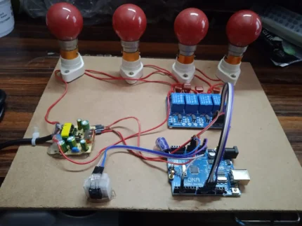
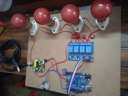
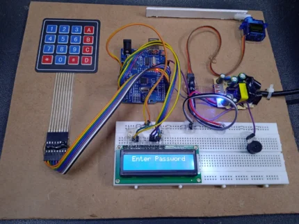
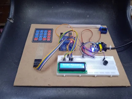
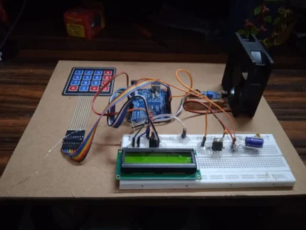
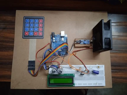
The Arduino-based mobile charging timer is a standalone electronic device designed to provide timed power control. At its heart, an Arduino microcontroller orchestrates the interactions between various modules: a joystick for user input, a 16×2 LCD for displaying information, and a relay module for switching the AC power supply. The user interface is intuitive, allowing for easy adjustment of hours, minutes, and seconds using the joystick. Once the desired time is set and the timer initiated, a real-time countdown is displayed on the LCD. Upon completion of the countdown, the relay deactivates, cutting off power to the connected appliance. This modular design makes the project highly adaptable, enabling its use for a wide range of applications beyond just mobile charging, such as controlling lights, fans, or other electrical devices.
3. Components Used
The successful operation of this project relies on the synergistic interaction of several key electronic components. Each component plays a vital role in the device’s overall functionality:
3.1. Arduino Microcontroller (e.g., Arduino Uno)
- Role: The brain of the entire system. The Arduino processes user input from the joystick, calculates and manages the countdown timer, controls the display on the LCD, and sends commands to the relay module to switch power.
- Working Principle: The Arduino board is built around an ATmega microcontroller. It features digital and analog input/output pins that can be programmed to interact with various electronic components. For this project, it reads analog values from the joystick, sends character data to the LCD via digital pins, and toggles a digital pin to control the relay. Its internal clock allows for precise timekeeping.
3.2. 16×2 LCD (Liquid Crystal Display)
- Role: Provides visual feedback to the user, displaying the set time, the real-time countdown, and operational messages. The “16×2” signifies that it can display 16 characters per line across two lines.
- Working Principle: LCDs work by selectively blocking or transmitting light. Each character on the display is formed by a matrix of pixels. The Arduino communicates with the LCD using a parallel interface (typically 4-bit or 8-bit mode) or a serial interface (using an I2C adapter for fewer wires). It sends commands to initialize the display, set the cursor position, and write characters.
3.3. Joystick Module (Analog Joystick)
- Role: Serves as the primary user input mechanism for setting the timer duration (hours, minutes, seconds) and initiating/pausing the timer.
- Working Principle: A typical joystick module consists of two potentiometers (one for X-axis movement, one for Y-axis movement) and a push button. As the joystick is moved, the resistance of the potentiometers changes, resulting in varying analog voltage outputs. The Arduino reads these analog voltages and converts them into numerical values, allowing it to determine the joystick’s position (e.g., up, down, left, right). The push button provides an additional digital input for selection or confirmation.
3.4. Relay Module
- Role: Acts as an electrically operated switch that can turn on or off a much larger current or voltage circuit using a small control current from the Arduino. In this project, it’s used to switch the 220V AC power supply to the mobile charger or appliance.
- Working Principle: A relay consists of an electromagnet, a coil, and a set of electrical contacts. When a small current from the Arduino flows through the relay’s coil, it creates a magnetic field that attracts an armature, causing the contacts to either close (normally open, NO) or open (normally closed, NC). For this application, a normally open contact is typically used, meaning power is supplied when the relay is energized by the Arduino.
3.5. 5V Power Supply
- Role: Provides the necessary direct current (DC) power to operate the Arduino board and all connected modules (LCD, joystick, relay module’s control circuit).
- Working Principle: This could be a USB power adapter, a dedicated 5V wall adapter, or even a battery pack with a voltage regulator. It converts the incoming AC voltage (if using a wall adapter) to a stable 5V DC output, which is the standard operating voltage for most Arduino-compatible components.
3.6. Breadboard
- Role: A solderless construction base used for prototyping electronic circuits. It allows for easy connection and disconnection of components without permanent soldering.
- Working Principle: The breadboard has rows and columns of interconnected holes. Components are inserted into these holes, and jumper wires are used to create electrical connections between them. This facilitates quick assembly, testing, and modification of the circuit.
4. Circuit Diagram (Conceptual Description)
While a visual diagram cannot be provided, the conceptual wiring of the components is straightforward:
- Arduino Power: The Arduino board is powered by the 5V power supply, typically via its USB port or DC barrel jack.
- LCD Connection:
- The LCD’s VCC and GND pins are connected to the Arduino’s 5V and GND pins, respectively.
- The RS (Register Select) and EN (Enable) pins of the LCD are connected to digital pins on the Arduino (e.g., D12, D11).
- The D4, D5, D6, D7 (data pins) of the LCD are connected to other digital pins on the Arduino (e.g., D5, D4, D3, D2).
- A potentiometer is usually connected to the LCD’s VO pin for contrast adjustment.
- The LED+ and LED- pins (for backlight) are connected to 5V and GND, often with a current-limiting resistor.
- Joystick Module Connection:
- The joystick’s VCC and GND pins are connected to the Arduino’s 5V and GND.
- The VRx (X-axis analog output) and VRy (Y-axis analog output) pins are connected to analog input pins on the Arduino (e.g., A0, A1).
- The SW (switch/button) pin is connected to a digital input pin on the Arduino (e.g., D6), usually with an internal pull-up resistor enabled or an external pull-up/pull-down resistor.
- Relay Module Connection:
- The relay module’s VCC and GND pins are connected to the Arduino’s 5V and GND.
- The IN (input/control) pin of the relay module is connected to a digital output pin on the Arduino (e.g., D7). When this pin goes HIGH, the relay activates.
- The AC appliance (e.g., mobile charger) is connected to the relay’s common (COM) and normally open (NO) terminals. The 220V AC live wire is cut, and one end is connected to COM, the other to NO. This ensures that when the relay is activated, the circuit is completed, and power flows to the appliance. Crucially, extreme caution must be exercised when dealing with 220V AC power.
5. Working Principle
The operation of the Arduino-based mobile charging timer can be broken down into several distinct phases:
5.1. Initialization
Upon power-up, the Arduino executes its programmed sketch.
- The LCD is initialized, and a welcome message or an initial time setting (e.g., “Set Time: 00:00:00”) is displayed.
- All necessary pins for the LCD, joystick, and relay are configured as inputs or outputs.
- Internal variables for hours, minutes, and seconds are set to zero.
- The relay is initially in the OFF state (power disconnected from the appliance).
5.2. Time Setting with Joystick
This is the primary user interaction phase.
- The Arduino continuously reads the analog values from the joystick’s X and Y axes, as well as the state of its push button.
- Navigation: Moving the joystick left or right might select which time unit (hours, minutes, seconds) is currently being adjusted. The selected unit could be indicated by a blinking cursor or a highlighted segment on the LCD.
- Adjustment: Moving the joystick up or down increments or decrements the value of the currently selected time unit. For example, pushing up increases hours, pushing down decreases hours.
- Confirmation/Selection: Pressing the joystick button can serve multiple purposes:
- Confirming the selection of a time unit to adjust.
- Moving to the next time unit after setting the current one.
- Confirming the entire time setting and moving to the “Start” state.
- The LCD updates in real-time to show the time being set by the user.
5.3. Starting the Charging/Timer
Once the user has set the desired duration and confirmed it (e.g., by pressing the joystick button after setting seconds, or selecting a “Start” option):
- The Arduino stores the set hours, minutes, and seconds.
- A “Charging…” or “Timer ON” message appears on the LCD.
- Crucially, the Arduino sends a HIGH signal to the relay module’s control pin. This energizes the relay, closing its normally open contacts and allowing 220V AC power to flow to the connected mobile charger or appliance.
- The internal countdown timer begins.
5.4. Countdown Display and Real-time Update
- The Arduino continuously decrements the time. This is typically managed using the
millis()function to avoid blocking delays, allowing the microcontroller to perform other tasks (like reading joystick input for potential pause/cancel functions) while timing. - Every second, the LCD display is updated to show the remaining time in
HH:MM:SSformat. This real-time feedback is essential for the user. - The display might also show a small indicator that charging is active.
5.5. Timer Completion and Relay Deactivation
- The Arduino constantly checks if the countdown timer has reached zero (00:00:00).
- Once the time expires:
- The Arduino sends a LOW signal to the relay module’s control pin. This de-energizes the relay, opening its contacts and cutting off the 220V AC power supply to the mobile charger/appliance.
- A “Charging Complete” or “Timer OFF” message is displayed on the LCD.
- The system might then revert to the initial time-setting mode or enter a standby state, awaiting further user input.
6. Arduino Code Logic (Conceptual Description)
The Arduino sketch would involve several key programming concepts and structures:
- Libraries:
LiquidCrystal.h: For controlling the 16×2 LCD.- No specific joystick library is usually needed; direct analog reads are sufficient.
- Global Variables:
int hours, minutes, seconds;: To store the set time.long startTime;: To store themillis()value when the timer starts.long elapsedTime;: To track the elapsed time during countdown.int relayPin;: The digital pin connected to the relay.int joyXPin, joyYPin, joySWPin;: Analog/digital pins for the joystick.enum State { SET_TIME, COUNTDOWN, COMPLETE };: A state machine to manage the different modes of operation.State currentState;: Variable to hold the current state.
setup()function:- Initialize
Serial.begin()for debugging (optional). - Initialize
lcd.begin(). - Set
pinMode()for relay (OUTPUT) and joystick switch (INPUT_PULLUP). - Set initial
currentState = SET_TIME. - Display initial message on LCD.
- Initialize
loop()function: This is where the main program logic resides, typically implemented as a state machine:if (currentState == SET_TIME):- Read joystick X, Y, and SW values.
- Implement logic to navigate between hours, minutes, seconds based on X-axis movement.
- Implement logic to increment/decrement the selected time unit based on Y-axis movement.
- Implement logic for the joystick button press to confirm selection or transition to
COUNTDOWNstate. - Update LCD to show the time being set.
else if (currentState == COUNTDOWN):- Calculate
elapsedTime = millis() - startTime;. - Calculate
remainingTime = (setHours*3600 + setMinutes*60 + setSeconds) - (elapsedTime / 1000);. - Convert
remainingTimeback intoHH:MM:SSformat. - Update LCD with the countdown.
- Check if
remainingTime <= 0. If true, setcurrentState = COMPLETE. - (Optional) Check joystick button for a “pause” or “cancel” function.
- Calculate
else if (currentState == COMPLETE):- Turn off the relay (
digitalWrite(relayPin, LOW)). - Display “Charging Complete” on LCD.
- (Optional) Wait for a button press to reset to
SET_TIMEstate.
- Turn off the relay (
- Helper Functions:
void updateLCD(): Encapsulates the logic for displaying time or messages on the LCD.void readJoystick(): Reads and debounces joystick inputs.void controlRelay(bool state): A simple function to turn the relay ON/OFF.
The use of millis() for timing is crucial for a non-blocking program, allowing the Arduino to continuously monitor joystick input even while the timer is running.
7. Advantages of the Project
This Arduino-based timer offers several significant advantages:
- Overcharge Prevention: The primary benefit for mobile charging is preventing the device from being continuously charged after reaching full capacity, which can contribute to battery degradation over time.
- Energy Saving: By automatically cutting off power, the device eliminates phantom load (power consumed by chargers even when not actively charging) and reduces overall energy consumption.
- Versatility and Adaptability: The core functionality of timed power control makes this project highly versatile. By simply changing the appliance connected to the relay, it can be used for a multitude of other applications.
- Simplicity and Cost-Effectiveness: The project utilizes readily available and inexpensive electronic components, making it an accessible and affordable solution for home automation or educational purposes.
- Customizable Duration: Users have precise control over the charging or operation duration, from seconds to multiple hours, providing flexibility for various needs.
- Educational Value: It serves as an excellent hands-on learning experience for electronics, programming, and embedded systems, demonstrating concepts like input/output, real-time control, and state machines.
8. Potential Applications and Extensions
The fundamental principle of a timed power switch opens doors to numerous applications beyond just mobile charging:
8.1. Beyond Mobile Charging
- Home Appliance Control:
- Lights: Turn off lights automatically after a set period (e.g., in a child’s room, a garage, or a storage area).
- Fans/Heaters: Operate fans or portable heaters for a specific duration to save energy.
- Kitchen Appliances: Control coffee makers, toasters, or slow cookers for precise cooking times.
- Water Pumps: Automate irrigation systems for gardens or small farms, ensuring plants receive water for a set period.
- Laboratory/Hobby Timers:
- Control experimental setups requiring precise timing.
- Manage exposure times for photographic darkroom processes.
- Automate processes in DIY projects, like turning on/off soldering irons or glue guns.
- Security/Safety:
- Timed activation of security lights.
- Ensuring certain devices are not left on indefinitely.
8.2. Potential Extensions and Enhancements
- Battery Level Detection: Integrate a voltage divider or a dedicated battery management IC to detect the mobile phone’s battery level and automatically stop charging when it reaches 100%, regardless of time. This would require more advanced circuitry and software.
- Remote Control: Add a Bluetooth module (HC-05/06) or an ESP8266 Wi-Fi module to allow users to set and monitor the timer via a smartphone app or web interface.
- Multiple Presets: Allow users to save frequently used timer durations as presets (e.g., “1 Hour,” “30 Minutes”) for quick selection.
- Alarm/Notification: Incorporate a small buzzer or LED to provide an audible or visual alert when the timer completes.
- RTC Module Integration: For greater accuracy and persistence across power cycles, integrate a Real-Time Clock (RTC) module (e.g., DS3231). This would also allow for scheduling events at specific times of day.
- Improved User Interface:
- Use a rotary encoder with a push button for more precise and faster time setting.
- Upgrade to a graphical LCD (GLCD) for a more visually appealing interface with custom icons and fonts.
- Add more buttons for dedicated functions (Start, Stop, Reset).
- Current/Power Monitoring: Integrate a current sensor (e.g., ACS712) to monitor the actual charging current or power consumption, displaying it on the LCD.
9. Challenges and Considerations
While the project is relatively straightforward, certain aspects require careful consideration:
- Power Consumption of Components: Although Arduino and basic modules consume little power, continuous operation can drain batteries if the device is meant to be portable. For permanent installations, a stable 5V wall adapter is ideal.
- Accuracy of the Timer: The Arduino’s internal clock is generally accurate enough for this application. However, for highly precise timing requirements over long durations, an external RTC module would be beneficial.
- Safety Precautions (220V AC): This is the most critical aspect. When dealing with 220V AC power, extreme caution is paramount.
- Proper Insulation: Ensure all high-voltage connections are properly insulated to prevent accidental contact.
- Enclosure: The entire circuit, especially the relay and AC wiring, should be housed in a non-conductive, fire-retardant enclosure to prevent accidental contact and contain any potential electrical faults.
- Fusing: Consider adding a fuse in the AC line before the relay to protect against overcurrents.
- Grounding: Ensure proper grounding practices if applicable.
- Qualified Assistance: If unsure about handling AC wiring, seek assistance from a qualified electrician.
- User Interface Improvements: While the joystick is functional, it can be cumbersome for setting very long durations. As mentioned in extensions, alternative input methods could enhance usability.
- Debouncing: Joystick button presses and movements can sometimes register multiple times due to mechanical bounce. Implementing software debouncing (checking the state after a small delay) is essential for reliable input.
10. Conclusion
The Arduino-based mobile charging timer is a practical, effective, and educational project that successfully addresses the need for timed power control. By integrating an Arduino microcontroller with a joystick for user input, an LCD for real-time feedback, and a relay for power switching, the device offers a versatile solution for preventing overcharging of mobile phones and managing the operation duration of various 220V appliances.
Its modular design, coupled with the open-source nature of Arduino, makes it highly customizable and extensible. From basic overcharge protection to advanced home automation, the foundational principles demonstrated in this project can be scaled and adapted to numerous real-world applications. While safety considerations, particularly concerning AC power, are paramount, the project stands as a testament to the power of microcontrollers in creating intelligent and efficient solutions for everyday challenges. This timer is not just a charging device; it’s a stepping stone into the vast possibilities of embedded systems and smart control.


Reviews
There are no reviews yet.